US9444522B2 - Near field communications (NFC) coil and proximity sensor for portable devices - Google Patents
Near field communications (NFC) coil and proximity sensor for portable devices Download PDFInfo
- Publication number
- US9444522B2 US9444522B2 US14/717,093 US201514717093A US9444522B2 US 9444522 B2 US9444522 B2 US 9444522B2 US 201514717093 A US201514717093 A US 201514717093A US 9444522 B2 US9444522 B2 US 9444522B2
- Authority
- US
- United States
- Prior art keywords
- nfc
- loop antenna
- proximity sensing
- circuitry
- electronic device
- Prior art date
- Legal status (The legal status is an assumption and is not a legal conclusion. Google has not performed a legal analysis and makes no representation as to the accuracy of the status listed.)
- Active
Links
- 238000004891 communication Methods 0.000 title claims abstract description 36
- 238000000034 method Methods 0.000 claims abstract description 26
- 239000003990 capacitor Substances 0.000 claims description 16
- 230000008569 process Effects 0.000 claims description 15
- 238000001914 filtration Methods 0.000 claims 2
- 230000006870 function Effects 0.000 abstract description 18
- 230000008878 coupling Effects 0.000 abstract description 13
- 238000010168 coupling process Methods 0.000 abstract description 13
- 238000005859 coupling reaction Methods 0.000 abstract description 13
- 238000001514 detection method Methods 0.000 description 10
- 238000012546 transfer Methods 0.000 description 7
- 230000008859 change Effects 0.000 description 5
- 230000005540 biological transmission Effects 0.000 description 4
- 238000005516 engineering process Methods 0.000 description 4
- 238000010586 diagram Methods 0.000 description 3
- 238000012545 processing Methods 0.000 description 3
- 238000007792 addition Methods 0.000 description 2
- 238000004590 computer program Methods 0.000 description 2
- 238000012986 modification Methods 0.000 description 2
- 230000004048 modification Effects 0.000 description 2
- 238000010521 absorption reaction Methods 0.000 description 1
- 230000004913 activation Effects 0.000 description 1
- 230000001413 cellular effect Effects 0.000 description 1
- 230000001010 compromised effect Effects 0.000 description 1
- 239000004020 conductor Substances 0.000 description 1
- 230000009849 deactivation Effects 0.000 description 1
- 238000007599 discharging Methods 0.000 description 1
- 238000009434 installation Methods 0.000 description 1
- 238000002955 isolation Methods 0.000 description 1
- 230000003287 optical effect Effects 0.000 description 1
- 230000001105 regulatory effect Effects 0.000 description 1
- 230000004044 response Effects 0.000 description 1
Images


Classifications
-
- H04B5/0043—
-
- H—ELECTRICITY
- H04—ELECTRIC COMMUNICATION TECHNIQUE
- H04B—TRANSMISSION
- H04B5/00—Near-field transmission systems, e.g. inductive or capacitive transmission systems
- H04B5/70—Near-field transmission systems, e.g. inductive or capacitive transmission systems specially adapted for specific purposes
- H04B5/73—Near-field transmission systems, e.g. inductive or capacitive transmission systems specially adapted for specific purposes for taking measurements, e.g. using sensing coils
-
- G—PHYSICS
- G06—COMPUTING; CALCULATING OR COUNTING
- G06K—GRAPHICAL DATA READING; PRESENTATION OF DATA; RECORD CARRIERS; HANDLING RECORD CARRIERS
- G06K7/00—Methods or arrangements for sensing record carriers, e.g. for reading patterns
- G06K7/10—Methods or arrangements for sensing record carriers, e.g. for reading patterns by electromagnetic radiation, e.g. optical sensing; by corpuscular radiation
- G06K7/10009—Methods or arrangements for sensing record carriers, e.g. for reading patterns by electromagnetic radiation, e.g. optical sensing; by corpuscular radiation sensing by radiation using wavelengths larger than 0.1 mm, e.g. radio-waves or microwaves
- G06K7/10237—Methods or arrangements for sensing record carriers, e.g. for reading patterns by electromagnetic radiation, e.g. optical sensing; by corpuscular radiation sensing by radiation using wavelengths larger than 0.1 mm, e.g. radio-waves or microwaves the reader and the record carrier being capable of selectively switching between reader and record carrier appearance, e.g. in near field communication [NFC] devices where the NFC device may function as an RFID reader or as an RFID tag
-
- H—ELECTRICITY
- H04—ELECTRIC COMMUNICATION TECHNIQUE
- H04B—TRANSMISSION
- H04B1/00—Details of transmission systems, not covered by a single one of groups H04B3/00 - H04B13/00; Details of transmission systems not characterised by the medium used for transmission
- H04B1/005—Details of transmission systems, not covered by a single one of groups H04B3/00 - H04B13/00; Details of transmission systems not characterised by the medium used for transmission adapting radio receivers, transmitters andtransceivers for operation on two or more bands, i.e. frequency ranges
- H04B1/0053—Details of transmission systems, not covered by a single one of groups H04B3/00 - H04B13/00; Details of transmission systems not characterised by the medium used for transmission adapting radio receivers, transmitters andtransceivers for operation on two or more bands, i.e. frequency ranges with common antenna for more than one band
- H04B1/006—Details of transmission systems, not covered by a single one of groups H04B3/00 - H04B13/00; Details of transmission systems not characterised by the medium used for transmission adapting radio receivers, transmitters andtransceivers for operation on two or more bands, i.e. frequency ranges with common antenna for more than one band using switches for selecting the desired band
-
- H04B5/0012—
-
- H04B5/0031—
-
- H04B5/0081—
-
- H—ELECTRICITY
- H04—ELECTRIC COMMUNICATION TECHNIQUE
- H04B—TRANSMISSION
- H04B5/00—Near-field transmission systems, e.g. inductive or capacitive transmission systems
- H04B5/20—Near-field transmission systems, e.g. inductive or capacitive transmission systems characterised by the transmission technique; characterised by the transmission medium
- H04B5/22—Capacitive coupling
-
- H—ELECTRICITY
- H04—ELECTRIC COMMUNICATION TECHNIQUE
- H04B—TRANSMISSION
- H04B5/00—Near-field transmission systems, e.g. inductive or capacitive transmission systems
- H04B5/20—Near-field transmission systems, e.g. inductive or capacitive transmission systems characterised by the transmission technique; characterised by the transmission medium
- H04B5/24—Inductive coupling
- H04B5/26—Inductive coupling using coils
-
- H—ELECTRICITY
- H04—ELECTRIC COMMUNICATION TECHNIQUE
- H04B—TRANSMISSION
- H04B5/00—Near-field transmission systems, e.g. inductive or capacitive transmission systems
- H04B5/70—Near-field transmission systems, e.g. inductive or capacitive transmission systems specially adapted for specific purposes
- H04B5/72—Near-field transmission systems, e.g. inductive or capacitive transmission systems specially adapted for specific purposes for local intradevice communication
-
- H—ELECTRICITY
- H04—ELECTRIC COMMUNICATION TECHNIQUE
- H04B—TRANSMISSION
- H04B5/00—Near-field transmission systems, e.g. inductive or capacitive transmission systems
- H04B5/70—Near-field transmission systems, e.g. inductive or capacitive transmission systems specially adapted for specific purposes
- H04B5/75—Near-field transmission systems, e.g. inductive or capacitive transmission systems specially adapted for specific purposes for isolation purposes
-
- H—ELECTRICITY
- H04—ELECTRIC COMMUNICATION TECHNIQUE
- H04L—TRANSMISSION OF DIGITAL INFORMATION, e.g. TELEGRAPHIC COMMUNICATION
- H04L25/00—Baseband systems
- H04L25/02—Details ; arrangements for supplying electrical power along data transmission lines
- H04L25/03—Shaping networks in transmitter or receiver, e.g. adaptive shaping networks
- H04L25/03006—Arrangements for removing intersymbol interference
-
- H04W4/008—
-
- H—ELECTRICITY
- H04—ELECTRIC COMMUNICATION TECHNIQUE
- H04W—WIRELESS COMMUNICATION NETWORKS
- H04W4/00—Services specially adapted for wireless communication networks; Facilities therefor
- H04W4/80—Services using short range communication, e.g. near-field communication [NFC], radio-frequency identification [RFID] or low energy communication
-
- H—ELECTRICITY
- H04—ELECTRIC COMMUNICATION TECHNIQUE
- H04L—TRANSMISSION OF DIGITAL INFORMATION, e.g. TELEGRAPHIC COMMUNICATION
- H04L25/00—Baseband systems
- H04L25/02—Details ; arrangements for supplying electrical power along data transmission lines
- H04L25/03—Shaping networks in transmitter or receiver, e.g. adaptive shaping networks
- H04L25/03006—Arrangements for removing intersymbol interference
- H04L2025/0335—Arrangements for removing intersymbol interference characterised by the type of transmission
- H04L2025/03375—Passband transmission
Definitions
- near field coupling such as wireless power transfers (WPT) and near field communications (NFC)
- WPT wireless power transfers
- NFC near field communications
- RF radio frequency
- Many of these portable wireless devices are small, and are becoming smaller as markets evolve, and tend to have exaggerated aspect ratios when viewed from the side.
- many thin portable devices incorporate flat antennas, which use coils of conductive material as their radiating antennas for use in near field coupling functions.
- (capacitive) proximity sensors may be used in tablets (portable device) with embedded wireless wide-area network (WWAN), such as a third generation or a fourth generation (3G/4G) digital radio, in order to pass Federal Communications Commission (FCC) regulations such as, specific absorption rate (SAR).
- WWAN wireless wide-area network
- FCC Federal Communications Commission
- SAR specific absorption rate
- the proximity sensors may detect human body within proximity, and may use a sensor electrode of relatively large size to implement proximity detection.
- Both the NFC and the proximity sensor devices may require significant space in a portable device and neither may be covered by metallic chassis/shielding. In other words, the NFC and the proximity sensor devices may be competing for a very limited space for antennas on the wireless device (e.g., tablets). The limited space even becomes more challenging as the portable device gets thinner and adopts a full metallic chassis.
- FIG. 1A illustrates an example near field coupling arrangement between portable devices to perform near field communications (NFC) related functions.
- NFC near field communications
- FIG. 1B illustrates an example wireless communications arrangement between portable devices that includes proximity sensing operation.
- FIG. 2 is a diagram of an example portable device.
- FIG. 3 is a diagram of an example proximity sensor circuit and near field communications (NFC) module combo that includes passive devices.
- NFC near field communications
- FIG. 4 is a diagram of an example proximity sensor circuit and near field communications (NFC) module combo that includes active devices.
- NFC near field communications
- FIG. 5 is a method for proximity sensing and near field communications using the same coil antenna.
- This document discloses one or more systems, apparatuses, methods, etc. for coupling antennas of devices and more particularly for using the same coil antenna of thin portable devices for proximity sensing and near field coupling capabilities of the portable devices.
- Near field coupling includes (by way of illustration and not limitation) wireless power transfer (WPT) and/or near field communications (NFC) capabilities of the portable devices.
- WPT wireless power transfer
- NFC near field communications
- a proximity sensor is integrated with a NFC module to form a single module.
- the single module may be connected to a coil antenna that receives an electrical signal for both proximity sensing operations and NFC operations.
- the proximity sensing operation may be configured to operate at a low frequency electrical signal (e.g., 30 KHz) to detect a human being within proximity, or to detect metallic components of another device within proximity range.
- the NFC operations may be configured to operate at a high frequency electrical signal (e.g., 13.56 MHz) to perform the NFC functions.
- the coil antenna is configured to include an open ended spiral shape coil antenna during proximity sensing operations by the proximity sensor.
- the coil antenna is configured to include a close ended spiral shape coil antenna to perform the NFC functions by the NFC module.
- passive devices or components may be installed to separate the proximity sensing operation from the NFC operations.
- the proximity sensing electrical signal is isolated from the NFC electrical signal.
- a software implementation uses active devices (e.g., switches) to separate the proximity sensing electrical signal from the NFC electrical signal.
- FIG. 1A illustrates an example arrangement of portable devices that performs NFC functions. More particularly, users may have a desire to operate near field coupling enabled portable electronic devices and/or other devices in certain ergonomically convenient manners. Examples of such portable devices include (but are not limited to) a mobile phone, a cellular phone, a smartphone, a personal digital assistant, a tablet computer, a netbook, a notebook computer, a laptop computer, a multimedia playback device, a digital music player, a digital video player, a navigational device, a digital camera, and the like.
- FIG. 1A shows a so-called “NFC bump” where two users (not shown) “bump” their NFC-enabled portable devices 102 - 2 and 102 - 4 together in an edge-to-edge or head-to-head manner to perform NFC-related information sharing functions.
- FIG. 1A shows an often desired side-by-side arrangement of the portable devices 102 for NFC purposes.
- the portable devices 102 - 2 and 102 - 4 may include a multiple loop (spiral shape) coil antenna (not shown) to perform the NFC operations.
- the NFC operations may include data communications between the portable devices 102 .
- the portable device 102 - 2 may transfer information to the portable device 102 - 4 through near filed coupling operations.
- FIG. 1B illustrates wireless communications between the portable device 102 - 2 and the portable device 102 - 4 .
- the portable devices 102 - 2 and 102 - 4 may include a proximity sensor circuit (not shown) that utilizes the multiple loop coil antenna to perform proximity sensing detection.
- the proximity sensing detection may be used to comply with FCC (and other) regulations such as, the SAR.
- the SAR may relate to regulatory limits regarding human exposure to electromagnetic energy from wireless devices such as the portable devices 102 .
- the portable devices 102 - 2 and 102 - 4 may include a wireless communications circuit (not shown) that includes one or more transceiver antennas (not shown).
- the wireless communication circuit may be configured to operate in accordance with one or more wireless standards.
- the wireless communication circuit may be configured to wirelessly transfer information between the portable device 102 - 2 and the portable device 102 - 4 via a wireless communication link 104 (through a tower 106 ) that is established in accordance with at least one of a 3G or 4G digital wireless communication standard.
- Such a 3G or 4G digital wireless communication standard may include one or more of a WiMax communication standard (e.g., in accordance with the IEEE 802.16 family of standards such as IEEE 802.16-2009), a Third-Generation Partnership Project (3GPP) Long-Term-Evolution (LTE) communication standard, or one or more other standards or protocols.
- the wireless communication circuit may be configured to wireless transfer information in accordance of a Wi-Fi wireless local-area-networking (WLAN) standard, such as one or more of the IEEE 802.11 family of standards (e.g., IEEE. 802.11a-1999, 802.11b-1999, 802.11g-2003, 802.11n-2009, 802.11-2007), or one or more other standards or protocols.
- WLAN Wi-Fi wireless local-area-networking
- the proximity sensing detection may allow the one or more transceiver antennas (not shown) at the portable device 102 to be at receive mode only if a human being (e.g., human being 108 ) is detected within proximity of the portable device 102 (e.g., portable device 102 - 2 ).
- the one or more transceiver antennas may regularly operate at transmitting and receiving mode if no human being 106 is detected by the proximity sensing detection.
- the transceiver antennas may be configured to throttle transmission power if the human being 108 is detected within proximity of the transceiver antennas.
- the proximity sensor circuit may utilize the multiple loop coil antenna to detect metallic components (not shown) of another portable device that may come within proximity of the portable device 102 - 2 . This information may be further used to initiate/cease wireless communication/wireless power transfer between the two devices.
- FIG. 2 is an example embodiment of the portable device 102 that utilizes the same coil antenna for NFC operations and proximity sensing detection.
- the wireless device 102 may include a transceiver (TX/RX) antenna 200 , a receiver (RX) antenna 202 , a NFC or proximity sensor coil antenna (NFC/Sensor coil antenna) 204 , a proximity sensor circuit and NFC module combo 206 , and a wireless communications circuit 208 .
- TX/RX transceiver
- RX receiver
- NFC or proximity sensor coil antenna NFC or proximity sensor coil antenna
- a proximity sensor circuit and NFC module combo 206 a wireless communications circuit 208 .
- the TX/RX antenna 200 and the NFC/Sensor coil antenna 204 may be located at one edge (e.g., top edge 210 ) of the portable device 102 .
- the RX antenna 202 may be located at another edge (e.g., bottom edge 212 ) of the portable device 102 .
- the NFC/Sensor coil antenna 204 may be configured to include an open ended spiral shape coil antenna to perform proximity sensing detection. For example, to detect presence or absence of human tissue in proximity to where the NFC/Sensor coil antenna 204 is located.
- the NFC/Sensor coil antenna 204 may be configured to include a close ended spiral shape coil antenna to perform NFC related functions such as, reading NFC tags, credit cards, or transfer of information using the “NFC bump” between two NFC enabled devices.
- the NFC/Sensor coil antenna 204 may carry, transmit, or receive an electrical signal that includes proximity sensing electrical (not shown) signal and NFC electrical signal (not shown).
- the proximity sensing electrical signal may include a change in capacitive characteristic due to a human being (e.g., human being 106 ) that comes within proximity, or due to metallic components of another device (e.g., portable device 102 - 2 , 102 - 4 ) that is within the proximity range of the NFC/Sensor coil antenna 204 .
- the proximity sensing electrical signal may include a low frequency of operation (e.g., 30 KHz) that may be separated from the NFC electrical signal that includes a high frequency of operation (e.g., 13.56 MHz) to perform NFC related functions.
- a low frequency of operation e.g., 30 KHz
- a high frequency of operation e.g. 13.56 MHz
- the proximity sensor circuit and NFC module combo 206 may be configured to process the received electrical signal from the NFC/Sensor coil antenna 204 .
- the proximity sensor circuit and NFC module combo 206 is a single module that includes a proximity sensor (not shown) and a NFC module (not shown).
- the proximity sensor processes the proximity sensing electrical signal, while the NFC module processes the NFC electrical signal.
- the proximity sensor circuit and NFC module combo 206 may be coupled to a wireless communications circuit 208 .
- the wireless communications circuit 208 may be configured to adjust the communication parameters such as, a transmit power, in response to information obtained from the proximity sensing operations.
- the adjustment of the TX/RX antenna 200 mode of operations may be implemented to comply with the SAR requirement of the FCC (and other).
- the proximity sensor circuit and NFC module combo 206 may be configured to process the received electrical signal from the NFC/Sensor coil antenna 204 and another NFC/Sensor coil antenna (not shown) that may be located at the edge 212 of the portable device 102 .
- the operation for the proximity sensor circuit and NFC module combo 206 discussed above is similarly applied; however, proximity sensing detection at the NFC/Sensor coil antenna (not shown) that is located at the edge 212 may be considered by the wireless communications circuit 208 in adjusting the communication parameters. For example, if a human is detected within proximity of the NFC/Sensor coil antenna 204 and the other NFC/Sensor coil antenna that is located at the edge 212 , transmission power is throttled in the portable device 102 .
- the portable device 102 may include a proximity sensor component (not shown) that may be integrated with an NFC module (not shown), and the NFC/Sensor coil antenna 204 to form a single module.
- the proximity sensor component may be used to detect presence of other near field coupling devices (e.g., portable device 102 - 2 , 102 - 4 ), or NFC tags/credit card that is within the proximity sensing range of the portable device 102 through detecting the capacitance change introduced by the metallic components within the other portable device, NFC tags, or credit card.
- the NFC/WPT module may be activated or deactivated in performing the NFC and/or WPT operations through the NFC/Sensor coil antenna 204 .
- the activation/deactivation of the NFC and/or WPT operations may avoid continuous RF emissions by the NFC module when no other near field coupling portable device (e.g., portable device 102 - 2 , 102 - 4 ) is within proximity range of the portable device 102 to reduce power consumption and RF emission.
- no other near field coupling portable device e.g., portable device 102 - 2 , 102 - 4
- the portable device 102 includes one or more processor(s) 214 .
- Processor(s) 214 may be a single processing unit or a number of processing units, all of which may include single or multiple computing units or multiple cores.
- the processor(s) 214 may be implemented as one or more microprocessors, microcomputers, microcontrollers, digital signal processors, central processing units, state machines, logic circuitries, and/or any devices that manipulate signals based on operational instructions.
- the processor(s) 214 may be configured to fetch and execute computer-readable instructions or processor-accessible instructions stored in a memory 216 or other computer-readable storage media.
- the memory component 216 is an example of computer-readable storage media for storing instructions, which are executed by the processor(s) 214 to perform the various functions described above.
- memory 216 may generally include both volatile memory and non-volatile memory (e.g., RAM, ROM, or the like).
- Memory 216 may be referred to as memory or computer-readable storage media herein.
- Memory 216 is capable of storing computer-readable, processor-executable program instructions as computer program code that may be executed by the processor(s) 214 as a particular machine configured for carrying out the operations and functions described in the implementations herein.
- the example portable device 102 described herein is merely an example that is suitable for some implementations and is not intended to suggest any limitation as to the scope of use or functionality of the environments, architectures and frameworks that may implement the processes, components and features described herein.
- any of the functions described with reference to the figures can be implemented using software, hardware (e.g., fixed logic circuitry) or a combination of these implementations.
- Program code may be stored in one or more computer-readable memory devices or other computer-readable storage devices.
- computer storage media includes volatile and non-volatile, removable and non-removable media implemented in any method or technology for storage of information, such as computer readable instructions, data structures, program modules, or other data.
- Computer storage media includes, but is not limited to, RAM, ROM, EEPROM, flash memory or other memory technology, CD-ROM, digital versatile disks (DVD) or other optical storage, magnetic cassettes, magnetic tape, magnetic disk storage or other magnetic storage devices, or any other medium that can be used to store information for access by a computing device.
- FIG. 3 is an example implementation 300 of proximity sensor and NFC module with passive devices.
- the emerging technologies related to near field coupling enable many appealing experiences for users of the portable device 102 .
- integrating a flexible printed circuit (FPC), which incorporates the NFC/Sensor coil antenna 204 , into a thin portable device 102 may minimize any increase in the thickness of the portable device 102 .
- FPC flexible printed circuit
- the drawing illustrates a proximity sensor 302 and a NFC module 304 that are integrated into a single module (i.e., Proximity sensor circuit and NFC module combo 206 ).
- the proximity sensor 302 may be configured to utilize the NFC/Sensor coil antenna 204 to carry the proximity sensing electrical signal.
- the NFC/Sensor coil antenna 204 may be utilized at the same time by the NFC module for NFC related functions, the proximity sensing electrical signal may be separated from the NFC electrical signal through installation of passive devices.
- the proximity sensor 302 may be configured to operate at a low frequency electrical signal such as, 30 KHz electrical signal for proximity sensing operations.
- the capacitive characteristic is measured by evaluating the charging and discharging current injected into the coil antenna 204 .
- the capacitive characteristic may change when a human comes in proximity with NFC/Sensor coil antenna 204 .
- the change in the capacitive characteristic may be compared to a configured threshold value for capacitance change that may trigger selection of the TX/RX antenna 200 or reduces TX power by the wireless communications circuitry 208 .
- the threshold value may similarly apply to changes in the capacitive characteristic due to metallic components of another portable device that is within proximity of the NFC/Sensor coil antenna 204 .
- the NFC/Sensor coil antenna 204 may be configured to include an open ended shape during proximity sensing operation.
- a terminal link 306 - 2 that is connected to one end of the NFC/Sensor coil antenna 204 may be connected to the proximity sensor 302 , and to a terminal of a front-end of the NFC module 304 .
- a second terminal link 306 - 4 that is connected to another end of the NFC/Sensor coil antenna 204 may be connected to another terminal of the NFC module 304 .
- the front-end terminals of the NFC module 304 are connected to capacitors 308 that link the NFC module 304 to the terminal connections 306 of the NFC/Sensor coil antenna 204 .
- the capacitors 308 may act as an open circuit (i.e., high isolation) to low frequency electrical signal (e.g., 30 KHz).
- low frequency electrical signal e.g., 30 KHz
- the terminal connections 306 - 2 and 306 - 4 are disconnected to the front-end of the NFC module 304 .
- a low pass filter that includes a passive device resistor 310 may act as a short circuit (i.e., low attenuation) to the 30 KHz proximity sensing electrical signal.
- the NFC/Sensor coil antenna 204 present to the Low frequency proximity sensing signal as an open ended spiral shape NFC/Sensor coil antenna 204 .
- the capacitors 308 may include a short circuit equivalent at relatively high operating frequency (e.g., 13.56 MHz for NFC operations).
- the low pass filter that links the NFC/Sensor coil antenna 204 to the proximity sensor 302 may offer an open circuit equivalent at the NFC operations frequency of 13.56 MHz.
- the low pass filter that links the proximity sensor 302 to the NFC/Sensor coil antenna 204 may isolate the high frequency NFC electrical signals. Accordingly, for NFC operations, the NFC/Sensor coil antenna 204 presents to the High frequency NFC signal as a closed spiral shape NFC/Sensor coil antenna 204 .
- FIG. 4 is an example implementation 400 of proximity sensor and NFC module with active devices.
- the active devices may be configured to include switches 402 - 2 and 402 - 4 to link the front-end terminals of the NFC module 304 to the NFC/Sensor coil antenna 204 .
- a switch 402 - 6 may be used to link the proximity sensor 302 to the terminal link 306 - 2 of the NFC/Sensor coil antenna 204 .
- the switches 402 - 2 and 402 - 4 may be configured to include an open circuit, while the switch 402 - 6 may be configured to include a short circuit.
- the NFC/Sensor coil antenna 204 is configured to include the open ended spiral shape during proximity sensing operation by the proximity sensor 302 .
- the switches 402 - 2 and 402 - 4 may be configured to include a short circuit, while the switch 402 - 6 may be configured to include an open circuit.
- the NFC/Sensor coil antenna 204 is configured to include the close ended spiral shape during the NFC operation by the NFC module 304 .
- the switches 402 may be dynamically controlled based on usage at the portable device 102 .
- the NFC/Sensor coil antenna 204 may be dedicated primarily for NFC related functions.
- the active devices i.e., switches 402
- the switches 402 may be configured to switch back and forth in a time domain between performing the proximity sensing detection at a certain time, and performing the NFC related functions at another time.
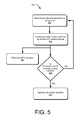
- FIG. 5 shows an example process chart illustrating an example method for proximity sensing and near field communications using the same coil antenna.
- the order in which the method is described is not intended to be construed as a limitation, and any number of the described method blocks can be combined in any order to implement the method, or alternate method. Additionally, individual blocks may be deleted from the method without departing from the spirit and scope of the subject matter described herein.
- the method may be implemented in any suitable hardware, software, firmware, or a combination thereof, without departing from the scope of the invention.
- a computer accessible medium may implement proximity sensing operations and NFC operations by utilizing the same coil antenna.
- the coil antenna may receive, carry, or transmit the electrical signal that includes a proximity sensing electrical signal and a NFC electrical signal.
- the proximity sensing electrical signal may include a low frequency of operation (e.g., 30 KHz) to implement proximity sensing operation.
- the NFC electrical signal may include a high frequency of operation (e.g., 13.56 MHz) to implement NFC related functions.
- passive devices may be used to separate the proximity sensing electrical signal from the NFC electrical signal.
- the use of passive devices i.e., capacitors 308 and resistor 310
- the use of the passive devices may include a high pass filter between a NFC module (e.g., NFC module 304 ) and the NFC/Sensor coil antenna 204 to allow the NFC electrical signal to the NFC module 304 while the proximity sensing electrical signal is blocked at the same time.
- a NFC module e.g., NFC module 304
- the NFC/Sensor coil antenna 204 may be used to allow the NFC electrical signal to the NFC module 304 while the proximity sensing electrical signal is blocked at the same time.
- the use of the passive devices or components may configure the NFC/Sensor coil antenna 204 to include an open ended spiral shape coil antenna configuration during proximity sensing operations.
- the passive devices may configure the NFC/Sensor coil antenna 204 to include a close ended spiral shape coil antenna configuration during NFC operations.
- use of active switches may be configured (e.g., by a software application) to isolate the proximity sensing electrical signal from the NFC electrical signal.
- the switches 402 may allow connection between the proximity sensor 302 and the NFC/Sensor coil antenna 204 while the NFC module 304 is disconnected to from the NFC/Sensor coil antenna 204 .
- NFC/Sensor coil antenna 204 is configured to include an open ended spiral shape coil antenna configuration during proximity sensing operations.
- the active switches 402 may be configured to transform the NFC/Sensor coil antenna 204 into a close ended spiral shape coil antenna configuration when the switches 402 disconnects the proximity sensor 302 from the NFC/Sensor coil antenna 204 while the NFC module is connected to the NFC/Sensor coil antenna 204 .
- performing NFC related function using the NFC electrical signal is performed.
- determining if threshold capacitance for proximity sensing operation is satisfied.
- the proximity sensor 302 processes a variation in capacitance due to a human in proximity of the NFC/Sensor coil antenna 204 .
- a threshold capacitance value may be configured to trigger selection of transceiver antenna (e.g., TX/RX antenna 200 ) or by adjusting the transmit power through a TX antenna (e.g. TX/RX antenna 200 ) by wireless communications circuitry to comply with SAR requirements. If the threshold capacitance value is satisfied, following the YES branch of block 510 , the adjustment of the transceiver antenna operation is performed.
- the NFC/Sensor coil antenna 204 continues to receive the electrical signal.
- the transceiver antennas may be configured to operate in transmit and receive mode at the same time, or at receive mode only, or in throttled transmission power state to comply with the SAR requirements.
Landscapes
- Engineering & Computer Science (AREA)
- Computer Networks & Wireless Communication (AREA)
- Signal Processing (AREA)
- Physics & Mathematics (AREA)
- Health & Medical Sciences (AREA)
- Toxicology (AREA)
- General Health & Medical Sciences (AREA)
- Electromagnetism (AREA)
- Artificial Intelligence (AREA)
- Computer Vision & Pattern Recognition (AREA)
- General Physics & Mathematics (AREA)
- Theoretical Computer Science (AREA)
- Power Engineering (AREA)
- Near-Field Transmission Systems (AREA)
- Telephone Function (AREA)
- Transceivers (AREA)
- User Interface Of Digital Computer (AREA)
- Support Of Aerials (AREA)
Abstract
Description
Claims (21)
Priority Applications (2)
| Application Number | Priority Date | Filing Date | Title |
|---|---|---|---|
| US14/717,093 US9444522B2 (en) | 2012-03-15 | 2015-05-20 | Near field communications (NFC) coil and proximity sensor for portable devices |
| US15/092,334 US9553637B2 (en) | 2012-03-15 | 2016-04-06 | Near field communications (NFC) and proximity sensor for portable devices |
Applications Claiming Priority (3)
| Application Number | Priority Date | Filing Date | Title |
|---|---|---|---|
| PCT/US2012/029301 WO2013137892A1 (en) | 2012-03-15 | 2012-03-15 | Near field co (nfc) and proximity sensor for portable devices |
| US201413977576A | 2014-04-21 | 2014-04-21 | |
| US14/717,093 US9444522B2 (en) | 2012-03-15 | 2015-05-20 | Near field communications (NFC) coil and proximity sensor for portable devices |
Related Parent Applications (2)
| Application Number | Title | Priority Date | Filing Date |
|---|---|---|---|
| US13/977,576 Continuation US9048882B2 (en) | 2012-03-15 | 2012-03-15 | Near field communications (NFC) and proximity sensor for portable devices |
| PCT/US2012/029301 Continuation WO2013137892A1 (en) | 2012-03-15 | 2012-03-15 | Near field co (nfc) and proximity sensor for portable devices |
Related Child Applications (1)
| Application Number | Title | Priority Date | Filing Date |
|---|---|---|---|
| US15/092,334 Continuation US9553637B2 (en) | 2012-03-15 | 2016-04-06 | Near field communications (NFC) and proximity sensor for portable devices |
Publications (2)
| Publication Number | Publication Date |
|---|---|
| US20150333802A1 US20150333802A1 (en) | 2015-11-19 |
| US9444522B2 true US9444522B2 (en) | 2016-09-13 |
Family
ID=49161623
Family Applications (3)
| Application Number | Title | Priority Date | Filing Date |
|---|---|---|---|
| US13/977,576 Active US9048882B2 (en) | 2012-03-15 | 2012-03-15 | Near field communications (NFC) and proximity sensor for portable devices |
| US14/717,093 Active US9444522B2 (en) | 2012-03-15 | 2015-05-20 | Near field communications (NFC) coil and proximity sensor for portable devices |
| US15/092,334 Active US9553637B2 (en) | 2012-03-15 | 2016-04-06 | Near field communications (NFC) and proximity sensor for portable devices |
Family Applications Before (1)
| Application Number | Title | Priority Date | Filing Date |
|---|---|---|---|
| US13/977,576 Active US9048882B2 (en) | 2012-03-15 | 2012-03-15 | Near field communications (NFC) and proximity sensor for portable devices |
Family Applications After (1)
| Application Number | Title | Priority Date | Filing Date |
|---|---|---|---|
| US15/092,334 Active US9553637B2 (en) | 2012-03-15 | 2016-04-06 | Near field communications (NFC) and proximity sensor for portable devices |
Country Status (6)
| Country | Link |
|---|---|
| US (3) | US9048882B2 (en) |
| EP (3) | EP3012981B1 (en) |
| JP (1) | JP5908644B2 (en) |
| CN (1) | CN104508687B (en) |
| BR (2) | BR122016030280A2 (en) |
| WO (1) | WO2013137892A1 (en) |
Cited By (3)
| Publication number | Priority date | Publication date | Assignee | Title |
|---|---|---|---|---|
| US9900055B1 (en) | 2017-02-01 | 2018-02-20 | Conduent Business Services, Llc | Magnetic presence detection of a smartphone |
| US9936466B1 (en) | 2017-02-17 | 2018-04-03 | Conduent Business Services, Llc | Bluetooth low energy collision management |
| US10652236B2 (en) | 2017-03-17 | 2020-05-12 | Conduent Business Services, Llc | Electronic crowd-based authentication |
Families Citing this family (160)
| Publication number | Priority date | Publication date | Assignee | Title |
|---|---|---|---|---|
| BR122016030280A2 (en) | 2012-03-15 | 2019-08-27 | Intel Corp | portable electronic device, electronic device and system |
| JP2014082735A (en) * | 2012-09-26 | 2014-05-08 | Panasonic Corp | Communication apparatus and electronic apparatus |
| US9619676B2 (en) * | 2012-12-05 | 2017-04-11 | Google Technology Holdings LLC | Touch sensor and radio frequency identification apparatus and method |
| DE102013102701A1 (en) * | 2013-03-18 | 2014-09-18 | Huf Hülsbeck & Fürst Gmbh & Co. Kg | Door handle assembly for a motor vehicle with capacitive proximity sensor and NFC transmitter / receiver unit |
| US9013300B2 (en) * | 2013-06-12 | 2015-04-21 | Wilfredo FELIX | Method of communicating information through a wearable device |
| US9495569B2 (en) * | 2013-12-20 | 2016-11-15 | General Electric Company | System and method to detect an event associated with a person relative to a bed |
| KR102189771B1 (en) | 2014-02-20 | 2020-12-11 | 삼성전자주식회사 | Electronic device and operating method thereof |
| US10597236B2 (en) * | 2014-04-15 | 2020-03-24 | Laitram, L.L.C. | Capacitively coupled conveyer measuring system |
| WO2016004134A2 (en) * | 2014-06-30 | 2016-01-07 | Libre Wireless Technologies, Inc. | Systems and techniques for wireless device configuration |
| WO2016008068A1 (en) * | 2014-07-14 | 2016-01-21 | 华为技术有限公司 | Method for controlling wearable electronic device, central apparatus and device |
| DE102014218213B4 (en) * | 2014-09-11 | 2017-09-28 | Continental Automotive Gmbh | Arrangement and method for detecting the approach of an object |
| US9993723B2 (en) * | 2014-09-25 | 2018-06-12 | Intel Corporation | Techniques for low power monitoring of sports game play |
| US9820513B2 (en) * | 2014-12-23 | 2017-11-21 | Intel Corporation | Depth proximity layering for wearable devices |
| US20160373166A1 (en) | 2015-06-17 | 2016-12-22 | Intel Corporation | Proximity sensor for deep sleep wakeup of wireless charger |
| JP6184580B1 (en) * | 2016-01-29 | 2017-08-23 | キヤノン株式会社 | Information processing apparatus, control method, and program |
| US9899879B2 (en) | 2016-02-15 | 2018-02-20 | Motorola Solutions, Inc. | Systems and methods for controlling wireless power transfer |
| FR3051578B1 (en) * | 2016-05-19 | 2018-05-25 | Continental Automotive France | NEAR FIELD COMMUNICATION DEVICE HAVING TWO NFC ZONES |
| EP3463067A1 (en) * | 2016-05-25 | 2019-04-10 | Martin Kuster | Electrocardiogram patch |
| TWI597624B (en) * | 2016-06-03 | 2017-09-01 | 凌通科技股份有限公司 | Integrated communication and capacitive sensing circuit and interactive system using the same |
| DE102016114595A1 (en) * | 2016-08-05 | 2018-02-08 | Huf Hülsbeck & Fürst Gmbh & Co. Kg | Method for detecting the approach of an access device for a locking system of a motor vehicle |
| US10879896B2 (en) * | 2016-09-07 | 2020-12-29 | Semtech Corporation | Capacitive proximity sensor in a mobile device and method of limiting radiation absorption |
| US11315114B2 (en) | 2016-12-28 | 2022-04-26 | Capital One Services, Llc | Dynamic transaction card protected by multi-factor authentication |
| US10267891B1 (en) | 2017-09-27 | 2019-04-23 | The United States Of America As Represented By The Secretary Of The Air Force | Rapid transfer of GNSS information from advantaged platform |
| DE102018104924B4 (en) * | 2018-03-05 | 2020-08-27 | Qundis Gmbh | Device with a radio communication unit and a switching unit |
| US10546444B2 (en) | 2018-06-21 | 2020-01-28 | Capital One Services, Llc | Systems and methods for secure read-only authentication |
| US11693519B2 (en) * | 2018-07-10 | 2023-07-04 | Sensortek Technology Corp. | Proximity sensor and proximity sensing method |
| TWI688164B (en) | 2018-08-21 | 2020-03-11 | 宏碁股份有限公司 | Detection device |
| DE102018122254B3 (en) | 2018-09-12 | 2019-12-12 | Ifm Electronic Gmbh | Capacitive door handle sensor with an antenna for near field communication |
| US11216806B2 (en) | 2018-09-19 | 2022-01-04 | Capital One Services, Llc | Systems and methods for providing card interactions |
| US10909527B2 (en) | 2018-10-02 | 2021-02-02 | Capital One Services, Llc | Systems and methods for performing a reissue of a contactless card |
| WO2020072575A1 (en) | 2018-10-02 | 2020-04-09 | Capital One Services, Llc | Systems and methods for cryptographic authentication of contactless cards |
| JP7595001B2 (en) | 2018-10-02 | 2024-12-05 | キャピタル・ワン・サービシーズ・リミテッド・ライアビリティ・カンパニー | System and method for cryptographic authentication of contactless cards - Patents.com |
| WO2020072552A1 (en) | 2018-10-02 | 2020-04-09 | Capital One Services, Llc | Systems and methods for cryptographic authentication of contactless cards |
| WO2020072694A1 (en) | 2018-10-02 | 2020-04-09 | Capital One Services, Llc | Systems and methods for cryptographic authentication of contactless cards |
| JP2022501861A (en) | 2018-10-02 | 2022-01-06 | キャピタル・ワン・サービシーズ・リミテッド・ライアビリティ・カンパニーCapital One Services, LLC | Systems and methods for cryptographic authentication of non-contact cards |
| CA3115142A1 (en) | 2018-10-02 | 2020-04-09 | Capital One Services, Llc | Systems and methods for cryptographic authentication of contactless cards |
| CA3115084A1 (en) | 2018-10-02 | 2020-04-09 | Capital One Services, Llc | Systems and methods for cryptographic authentication of contactless cards |
| US10733645B2 (en) | 2018-10-02 | 2020-08-04 | Capital One Services, Llc | Systems and methods for establishing identity for order pick up |
| US10579998B1 (en) | 2018-10-02 | 2020-03-03 | Capital One Services, Llc | Systems and methods for cryptographic authentication of contactless cards |
| KR20210065109A (en) | 2018-10-02 | 2021-06-03 | 캐피탈 원 서비시즈, 엘엘씨 | System and method for cryptographic authentication of contactless card |
| US11210664B2 (en) | 2018-10-02 | 2021-12-28 | Capital One Services, Llc | Systems and methods for amplifying the strength of cryptographic algorithms |
| US10607214B1 (en) | 2018-10-02 | 2020-03-31 | Capital One Services, Llc | Systems and methods for cryptographic authentication of contactless cards |
| MX2021003138A (en) | 2018-10-02 | 2021-05-14 | Capital One Services Llc | Systems and methods for cryptographic authentication of contactless cards. |
| CA3115107A1 (en) | 2018-10-02 | 2020-04-09 | Capital One Services, Llc | Systems and methods for cryptographic authentication of contactless cards |
| US10489781B1 (en) | 2018-10-02 | 2019-11-26 | Capital One Services, Llc | Systems and methods for cryptographic authentication of contactless cards |
| US10511443B1 (en) | 2018-10-02 | 2019-12-17 | Capital One Services, Llc | Systems and methods for cryptographic authentication of contactless cards |
| US10615981B1 (en) | 2018-10-02 | 2020-04-07 | Capital One Services, Llc | Systems and methods for cryptographic authentication of contactless cards |
| US10592710B1 (en) | 2018-10-02 | 2020-03-17 | Capital One Services, Llc | Systems and methods for cryptographic authentication of contactless cards |
| US10949520B2 (en) | 2018-10-02 | 2021-03-16 | Capital One Services, Llc | Systems and methods for cross coupling risk analytics and one-time-passcodes |
| US10771253B2 (en) | 2018-10-02 | 2020-09-08 | Capital One Services, Llc | Systems and methods for cryptographic authentication of contactless cards |
| US10554411B1 (en) | 2018-10-02 | 2020-02-04 | Capital One Services, Llc | Systems and methods for cryptographic authentication of contactless cards |
| US10581611B1 (en) | 2018-10-02 | 2020-03-03 | Capital One Services, Llc | Systems and methods for cryptographic authentication of contactless cards |
| US10783519B2 (en) | 2018-10-02 | 2020-09-22 | Capital One Services, Llc | Systems and methods for cryptographic authentication of contactless cards |
| US10771254B2 (en) | 2018-10-02 | 2020-09-08 | Capital One Services, Llc | Systems and methods for email-based card activation |
| KR20210069643A (en) | 2018-10-02 | 2021-06-11 | 캐피탈 원 서비시즈, 엘엘씨 | System and method for cryptographic authentication of contactless card |
| US10582386B1 (en) | 2018-10-02 | 2020-03-03 | Capital One Services, Llc | Systems and methods for cryptographic authentication of contactless cards |
| US10505738B1 (en) | 2018-10-02 | 2019-12-10 | Capital One Services, Llc | Systems and methods for cryptographic authentication of contactless cards |
| US10565587B1 (en) | 2018-10-02 | 2020-02-18 | Capital One Services, Llc | Systems and methods for cryptographic authentication of contactless cards |
| US10542036B1 (en) | 2018-10-02 | 2020-01-21 | Capital One Services, Llc | Systems and methods for signaling an attack on contactless cards |
| US10664830B1 (en) | 2018-12-18 | 2020-05-26 | Capital One Services, Llc | Devices and methods for selective contactless communication |
| US20200226581A1 (en) | 2019-01-11 | 2020-07-16 | Capital One Services, Llc | Systems and methods for touch screen interface interaction using a card overlay |
| US11037136B2 (en) | 2019-01-24 | 2021-06-15 | Capital One Services, Llc | Tap to autofill card data |
| US11120453B2 (en) | 2019-02-01 | 2021-09-14 | Capital One Services, Llc | Tap card to securely generate card data to copy to clipboard |
| US10510074B1 (en) | 2019-02-01 | 2019-12-17 | Capital One Services, Llc | One-tap payment using a contactless card |
| US10467622B1 (en) | 2019-02-01 | 2019-11-05 | Capital One Services, Llc | Using on-demand applications to generate virtual numbers for a contactless card to securely autofill forms |
| US10425129B1 (en) | 2019-02-27 | 2019-09-24 | Capital One Services, Llc | Techniques to reduce power consumption in near field communication systems |
| US10523708B1 (en) | 2019-03-18 | 2019-12-31 | Capital One Services, Llc | System and method for second factor authentication of customer support calls |
| US10643420B1 (en) | 2019-03-20 | 2020-05-05 | Capital One Services, Llc | Contextual tapping engine |
| US10438437B1 (en) | 2019-03-20 | 2019-10-08 | Capital One Services, Llc | Tap to copy data to clipboard via NFC |
| US10535062B1 (en) | 2019-03-20 | 2020-01-14 | Capital One Services, Llc | Using a contactless card to securely share personal data stored in a blockchain |
| US10984416B2 (en) | 2019-03-20 | 2021-04-20 | Capital One Services, Llc | NFC mobile currency transfer |
| US10970712B2 (en) | 2019-03-21 | 2021-04-06 | Capital One Services, Llc | Delegated administration of permissions using a contactless card |
| US10467445B1 (en) | 2019-03-28 | 2019-11-05 | Capital One Services, Llc | Devices and methods for contactless card alignment with a foldable mobile device |
| US11521262B2 (en) | 2019-05-28 | 2022-12-06 | Capital One Services, Llc | NFC enhanced augmented reality information overlays |
| US10516447B1 (en) | 2019-06-17 | 2019-12-24 | Capital One Services, Llc | Dynamic power levels in NFC card communications |
| FR3098067B1 (en) * | 2019-06-25 | 2022-12-23 | St Microelectronics Rousset | NFC device detection |
| US11694187B2 (en) | 2019-07-03 | 2023-07-04 | Capital One Services, Llc | Constraining transactional capabilities for contactless cards |
| US10871958B1 (en) | 2019-07-03 | 2020-12-22 | Capital One Services, Llc | Techniques to perform applet programming |
| US11392933B2 (en) | 2019-07-03 | 2022-07-19 | Capital One Services, Llc | Systems and methods for providing online and hybridcard interactions |
| US12086852B2 (en) | 2019-07-08 | 2024-09-10 | Capital One Services, Llc | Authenticating voice transactions with payment card |
| US10713649B1 (en) | 2019-07-09 | 2020-07-14 | Capital One Services, Llc | System and method enabling mobile near-field communication to update display on a payment card |
| US10885514B1 (en) | 2019-07-15 | 2021-01-05 | Capital One Services, Llc | System and method for using image data to trigger contactless card transactions |
| US10498401B1 (en) | 2019-07-15 | 2019-12-03 | Capital One Services, Llc | System and method for guiding card positioning using phone sensors |
| US10832271B1 (en) | 2019-07-17 | 2020-11-10 | Capital One Services, Llc | Verified reviews using a contactless card |
| US11182771B2 (en) | 2019-07-17 | 2021-11-23 | Capital One Services, Llc | System for value loading onto in-vehicle device |
| US10733601B1 (en) | 2019-07-17 | 2020-08-04 | Capital One Services, Llc | Body area network facilitated authentication or payment authorization |
| US11521213B2 (en) | 2019-07-18 | 2022-12-06 | Capital One Services, Llc | Continuous authentication for digital services based on contactless card positioning |
| US10506426B1 (en) | 2019-07-19 | 2019-12-10 | Capital One Services, Llc | Techniques for call authentication |
| US10541995B1 (en) | 2019-07-23 | 2020-01-21 | Capital One Services, Llc | First factor contactless card authentication system and method |
| TWI710164B (en) | 2019-08-19 | 2020-11-11 | 和碩聯合科技股份有限公司 | Electronic device |
| KR102717440B1 (en) | 2019-08-21 | 2024-10-16 | 삼성전자주식회사 | Electronic device adjusting output power of signal by using millimeter wave and method for controlling thereof |
| US11762624B2 (en) * | 2019-09-23 | 2023-09-19 | Sonos, Inc. | Capacitive touch sensor with integrated antenna(s) for playback devices |
| AU2019469080A1 (en) | 2019-10-02 | 2022-04-21 | Capital One Services, Llc | Client device authentication using contactless legacy magnetic stripe data |
| US10733283B1 (en) | 2019-12-23 | 2020-08-04 | Capital One Services, Llc | Secure password generation and management using NFC and contactless smart cards |
| US10862540B1 (en) | 2019-12-23 | 2020-12-08 | Capital One Services, Llc | Method for mapping NFC field strength and location on mobile devices |
| US10885410B1 (en) | 2019-12-23 | 2021-01-05 | Capital One Services, Llc | Generating barcodes utilizing cryptographic techniques |
| US11615395B2 (en) | 2019-12-23 | 2023-03-28 | Capital One Services, Llc | Authentication for third party digital wallet provisioning |
| US11113685B2 (en) | 2019-12-23 | 2021-09-07 | Capital One Services, Llc | Card issuing with restricted virtual numbers |
| US10657754B1 (en) | 2019-12-23 | 2020-05-19 | Capital One Services, Llc | Contactless card and personal identification system |
| US11651361B2 (en) | 2019-12-23 | 2023-05-16 | Capital One Services, Llc | Secure authentication based on passport data stored in a contactless card |
| US11200563B2 (en) | 2019-12-24 | 2021-12-14 | Capital One Services, Llc | Account registration using a contactless card |
| US10664941B1 (en) | 2019-12-24 | 2020-05-26 | Capital One Services, Llc | Steganographic image encoding of biometric template information on a card |
| US10853795B1 (en) | 2019-12-24 | 2020-12-01 | Capital One Services, Llc | Secure authentication based on identity data stored in a contactless card |
| US10909544B1 (en) | 2019-12-26 | 2021-02-02 | Capital One Services, Llc | Accessing and utilizing multiple loyalty point accounts |
| US10757574B1 (en) | 2019-12-26 | 2020-08-25 | Capital One Services, Llc | Multi-factor authentication providing a credential via a contactless card for secure messaging |
| US11038688B1 (en) | 2019-12-30 | 2021-06-15 | Capital One Services, Llc | Techniques to control applets for contactless cards |
| US10860914B1 (en) | 2019-12-31 | 2020-12-08 | Capital One Services, Llc | Contactless card and method of assembly |
| US11455620B2 (en) | 2019-12-31 | 2022-09-27 | Capital One Services, Llc | Tapping a contactless card to a computing device to provision a virtual number |
| EP3863185A1 (en) * | 2020-02-07 | 2021-08-11 | Nxp B.V. | Communication device and method for operating the same |
| EP3890196B1 (en) * | 2020-04-03 | 2023-06-21 | Nxp B.V. | Communication and wireless charging device and operating method |
| US11210656B2 (en) | 2020-04-13 | 2021-12-28 | Capital One Services, Llc | Determining specific terms for contactless card activation |
| US11030339B1 (en) | 2020-04-30 | 2021-06-08 | Capital One Services, Llc | Systems and methods for data access control of personal user data using a short-range transceiver |
| US11823175B2 (en) | 2020-04-30 | 2023-11-21 | Capital One Services, Llc | Intelligent card unlock |
| US11222342B2 (en) | 2020-04-30 | 2022-01-11 | Capital One Services, Llc | Accurate images in graphical user interfaces to enable data transfer |
| US10861006B1 (en) | 2020-04-30 | 2020-12-08 | Capital One Services, Llc | Systems and methods for data access control using a short-range transceiver |
| US10915888B1 (en) | 2020-04-30 | 2021-02-09 | Capital One Services, Llc | Contactless card with multiple rotating security keys |
| US10963865B1 (en) | 2020-05-12 | 2021-03-30 | Capital One Services, Llc | Augmented reality card activation experience |
| US11063979B1 (en) | 2020-05-18 | 2021-07-13 | Capital One Services, Llc | Enabling communications between applications in a mobile operating system |
| US11100511B1 (en) | 2020-05-18 | 2021-08-24 | Capital One Services, Llc | Application-based point of sale system in mobile operating systems |
| US11062098B1 (en) | 2020-08-11 | 2021-07-13 | Capital One Services, Llc | Augmented reality information display and interaction via NFC based authentication |
| US12165149B2 (en) | 2020-08-12 | 2024-12-10 | Capital One Services, Llc | Systems and methods for user verification via short-range transceiver |
| US11165586B1 (en) | 2020-10-30 | 2021-11-02 | Capital One Services, Llc | Call center web-based authentication using a contactless card |
| US11482312B2 (en) | 2020-10-30 | 2022-10-25 | Capital One Services, Llc | Secure verification of medical status using a contactless card |
| US11373169B2 (en) | 2020-11-03 | 2022-06-28 | Capital One Services, Llc | Web-based activation of contactless cards |
| US11968630B2 (en) * | 2020-11-06 | 2024-04-23 | Samsung Electronics Co., Ltd. | Electronic device having slidable structure |
| US11216799B1 (en) | 2021-01-04 | 2022-01-04 | Capital One Services, Llc | Secure generation of one-time passcodes using a contactless card |
| US11682012B2 (en) | 2021-01-27 | 2023-06-20 | Capital One Services, Llc | Contactless delivery systems and methods |
| US11792001B2 (en) | 2021-01-28 | 2023-10-17 | Capital One Services, Llc | Systems and methods for secure reprovisioning |
| US11687930B2 (en) | 2021-01-28 | 2023-06-27 | Capital One Services, Llc | Systems and methods for authentication of access tokens |
| US11562358B2 (en) | 2021-01-28 | 2023-01-24 | Capital One Services, Llc | Systems and methods for near field contactless card communication and cryptographic authentication |
| US11438329B2 (en) | 2021-01-29 | 2022-09-06 | Capital One Services, Llc | Systems and methods for authenticated peer-to-peer data transfer using resource locators |
| US11777933B2 (en) | 2021-02-03 | 2023-10-03 | Capital One Services, Llc | URL-based authentication for payment cards |
| US11637826B2 (en) | 2021-02-24 | 2023-04-25 | Capital One Services, Llc | Establishing authentication persistence |
| CN113036396A (en) * | 2021-03-04 | 2021-06-25 | 维沃移动通信有限公司 | Electronic device |
| US12143515B2 (en) | 2021-03-26 | 2024-11-12 | Capital One Services, Llc | Systems and methods for transaction card-based authentication |
| US11245438B1 (en) | 2021-03-26 | 2022-02-08 | Capital One Services, Llc | Network-enabled smart apparatus and systems and methods for activating and provisioning same |
| US12160419B2 (en) | 2021-04-15 | 2024-12-03 | Capital One Services, Llc | Authenticated messaging session with contactless card authentication |
| US11961089B2 (en) | 2021-04-20 | 2024-04-16 | Capital One Services, Llc | On-demand applications to extend web services |
| US11935035B2 (en) | 2021-04-20 | 2024-03-19 | Capital One Services, Llc | Techniques to utilize resource locators by a contactless card to perform a sequence of operations |
| US11902442B2 (en) | 2021-04-22 | 2024-02-13 | Capital One Services, Llc | Secure management of accounts on display devices using a contactless card |
| US11354555B1 (en) | 2021-05-04 | 2022-06-07 | Capital One Services, Llc | Methods, mediums, and systems for applying a display to a transaction card |
| US12301735B2 (en) | 2021-06-18 | 2025-05-13 | Capital One Services, Llc | Systems and methods for contactless card communication and multi-device key pair cryptographic authentication |
| US12041172B2 (en) | 2021-06-25 | 2024-07-16 | Capital One Services, Llc | Cryptographic authentication to control access to storage devices |
| US12061682B2 (en) | 2021-07-19 | 2024-08-13 | Capital One Services, Llc | System and method to perform digital authentication using multiple channels of communication |
| FR3126276B1 (en) * | 2021-08-19 | 2025-01-31 | Continental Automotive | Approach detection device |
| JP7642494B2 (en) | 2021-08-25 | 2025-03-10 | 株式会社東海理化電機製作所 | Authentication system and user interface device |
| JP7642493B2 (en) | 2021-08-25 | 2025-03-10 | 株式会社東海理化電機製作所 | Authentication system and user interface device |
| JP7642492B2 (en) | 2021-08-25 | 2025-03-10 | 株式会社東海理化電機製作所 | Authentication system and user interface device |
| US12147866B2 (en) | 2021-09-03 | 2024-11-19 | Snap-On Incorporated | Method and system for determining whether a dongle is in spatial proximity to a vehicle diagnostic tool |
| US12062258B2 (en) | 2021-09-16 | 2024-08-13 | Capital One Services, Llc | Use of a payment card to unlock a lock |
| CN113989963B (en) * | 2021-10-28 | 2024-11-26 | 维沃移动通信有限公司 | Signal processing method and related equipment |
| US12069173B2 (en) | 2021-12-15 | 2024-08-20 | Capital One Services, Llc | Key recovery based on contactless card authentication |
| US12166750B2 (en) | 2022-02-08 | 2024-12-10 | Capital One Services, Llc | Systems and methods for secure access of storage |
| US12289396B2 (en) | 2022-08-18 | 2025-04-29 | Capital One Services, Llc | Parallel secret salt generation and authentication for encrypted communication |
| US12147983B2 (en) | 2023-01-13 | 2024-11-19 | Capital One Services, Llc | Systems and methods for multi-factor authentication using device tracking and identity verification |
| US12248832B2 (en) | 2023-03-07 | 2025-03-11 | Capital One Services, Llc | Systems and methods for steganographic image encoding and identity verification using same |
| US12248928B2 (en) | 2023-03-13 | 2025-03-11 | Capital One Services, Llc | Systems and methods of secure merchant payment over messaging platform using a contactless card |
| US12124903B2 (en) | 2023-03-16 | 2024-10-22 | Capital One Services, Llc | Card with a time-sensitive element and systems and methods for implementing the same |
| US12299672B2 (en) | 2023-03-30 | 2025-05-13 | Capital One Services, Llc | System and method for authentication with transaction cards |
| US12200135B2 (en) | 2023-06-13 | 2025-01-14 | Capital One Services, Llc | Contactless card-based authentication via web-browser |
Citations (16)
| Publication number | Priority date | Publication date | Assignee | Title |
|---|---|---|---|---|
| US5956626A (en) | 1996-06-03 | 1999-09-21 | Motorola, Inc. | Wireless communication device having an electromagnetic wave proximity sensor |
| US20070222609A1 (en) | 2006-03-22 | 2007-09-27 | Symbol Technologies, Inc. | Single frequency low power RFID device |
| US20080081631A1 (en) | 2006-09-29 | 2008-04-03 | Ahmadreza Rofougaran | Method And System For Integrating An NFC Antenna And A BT/WLAN Antenna |
| US20080220831A1 (en) | 2007-03-06 | 2008-09-11 | Motorola, Inc. | Earmounted electronic device and method |
| US20090167699A1 (en) | 2007-12-27 | 2009-07-02 | Apple Inc. | Touch screen rfid tag reader |
| US20100084918A1 (en) | 2008-10-03 | 2010-04-08 | Access Business Group International Llc | Power system |
| US20100190436A1 (en) | 2008-08-26 | 2010-07-29 | Qualcomm Incorporated | Concurrent wireless power transmission and near-field communication |
| US20100201513A1 (en) | 2009-02-06 | 2010-08-12 | Broadcom Corporation | Efficiency indicator for increasing efficiency of wireless power transfer |
| US20110251892A1 (en) | 2010-04-09 | 2011-10-13 | Kevin Laracey | Mobile Phone Payment Processing Methods and Systems |
| US20110260882A1 (en) | 2010-04-22 | 2011-10-27 | Samsung Electronics Co. Ltd. | Method and apparatus for proximity sensing of a portable terminal |
| US20110293095A1 (en) | 2009-06-22 | 2011-12-01 | Mourad Ben Ayed | Systems for intelligent authentication based on proximity |
| WO2011155939A1 (en) | 2010-06-10 | 2011-12-15 | Empire Technology Development Llc | Communication between touch-panel devices |
| US20120313901A1 (en) | 2011-06-08 | 2012-12-13 | Cirque Corporation | Compensating for an antenna that is close enough to a touchpad to cause interference with touch sensor operation |
| WO2013137892A1 (en) | 2012-03-15 | 2013-09-19 | Intel Corporation | Near field co (nfc) and proximity sensor for portable devices |
| US20150303568A1 (en) * | 2014-04-16 | 2015-10-22 | Apple Inc. | Antennas for Near-Field and Non-Near-Field Communications |
| US9275791B2 (en) * | 2012-08-31 | 2016-03-01 | Qualcomm Incorporated | Systems and methods for decoupling multiple wireless charging transmitters |
Family Cites Families (2)
| Publication number | Priority date | Publication date | Assignee | Title |
|---|---|---|---|---|
| US8466839B2 (en) * | 2009-07-17 | 2013-06-18 | Apple Inc. | Electronic devices with parasitic antenna resonating elements that reduce near field radiation |
| JP5469445B2 (en) * | 2009-12-22 | 2014-04-16 | 株式会社メガチップス | COMMUNICATION DEVICE AND SENSOR SYSTEM WITH PROXIMITY SENSOR FUNCTION |
-
2012
- 2012-03-15 BR BR122016030280A patent/BR122016030280A2/en active Search and Examination
- 2012-03-15 JP JP2015500410A patent/JP5908644B2/en active Active
- 2012-03-15 EP EP15191310.0A patent/EP3012981B1/en active Active
- 2012-03-15 EP EP12871366.6A patent/EP2826000B1/en active Active
- 2012-03-15 WO PCT/US2012/029301 patent/WO2013137892A1/en active Application Filing
- 2012-03-15 EP EP16205517.2A patent/EP3197061A3/en not_active Withdrawn
- 2012-03-15 US US13/977,576 patent/US9048882B2/en active Active
- 2012-03-15 BR BR122016030290A patent/BR122016030290A2/en active Search and Examination
- 2012-03-15 CN CN201280071356.3A patent/CN104508687B/en active Active
-
2015
- 2015-05-20 US US14/717,093 patent/US9444522B2/en active Active
-
2016
- 2016-04-06 US US15/092,334 patent/US9553637B2/en active Active
Patent Citations (17)
| Publication number | Priority date | Publication date | Assignee | Title |
|---|---|---|---|---|
| US5956626A (en) | 1996-06-03 | 1999-09-21 | Motorola, Inc. | Wireless communication device having an electromagnetic wave proximity sensor |
| US20070222609A1 (en) | 2006-03-22 | 2007-09-27 | Symbol Technologies, Inc. | Single frequency low power RFID device |
| US20080081631A1 (en) | 2006-09-29 | 2008-04-03 | Ahmadreza Rofougaran | Method And System For Integrating An NFC Antenna And A BT/WLAN Antenna |
| US20080220831A1 (en) | 2007-03-06 | 2008-09-11 | Motorola, Inc. | Earmounted electronic device and method |
| US20090167699A1 (en) | 2007-12-27 | 2009-07-02 | Apple Inc. | Touch screen rfid tag reader |
| US20100190436A1 (en) | 2008-08-26 | 2010-07-29 | Qualcomm Incorporated | Concurrent wireless power transmission and near-field communication |
| US20100084918A1 (en) | 2008-10-03 | 2010-04-08 | Access Business Group International Llc | Power system |
| US20100201513A1 (en) | 2009-02-06 | 2010-08-12 | Broadcom Corporation | Efficiency indicator for increasing efficiency of wireless power transfer |
| US20110293095A1 (en) | 2009-06-22 | 2011-12-01 | Mourad Ben Ayed | Systems for intelligent authentication based on proximity |
| US20110251892A1 (en) | 2010-04-09 | 2011-10-13 | Kevin Laracey | Mobile Phone Payment Processing Methods and Systems |
| US20110260882A1 (en) | 2010-04-22 | 2011-10-27 | Samsung Electronics Co. Ltd. | Method and apparatus for proximity sensing of a portable terminal |
| WO2011155939A1 (en) | 2010-06-10 | 2011-12-15 | Empire Technology Development Llc | Communication between touch-panel devices |
| US20120313901A1 (en) | 2011-06-08 | 2012-12-13 | Cirque Corporation | Compensating for an antenna that is close enough to a touchpad to cause interference with touch sensor operation |
| WO2013137892A1 (en) | 2012-03-15 | 2013-09-19 | Intel Corporation | Near field co (nfc) and proximity sensor for portable devices |
| US9048882B2 (en) | 2012-03-15 | 2015-06-02 | Intel Corporation | Near field communications (NFC) and proximity sensor for portable devices |
| US9275791B2 (en) * | 2012-08-31 | 2016-03-01 | Qualcomm Incorporated | Systems and methods for decoupling multiple wireless charging transmitters |
| US20150303568A1 (en) * | 2014-04-16 | 2015-10-22 | Apple Inc. | Antennas for Near-Field and Non-Near-Field Communications |
Non-Patent Citations (6)
| Title |
|---|
| Extended European Search Report for European Publication No. 2826000, dated Sep. 22, 2015, 5 pages. |
| Extended European Search report received for European Patent Application No. 15191310.0, mailed on Jan. 20, 2016, 8 pages. |
| International Preliminary Report on Patentability and Written Opinion received for PCT Patent Application No. PCT/US2012/029301, mailed on Sep. 25, 2014, 6 pages. |
| International Search Report and Written Opinion received for PCT Patent Application No. PCT/US2012/029301, mailed on Nov. 16, 2012, 9 pages. |
| Office Action Received for Japanese Patent Application No. 2015-500410, mailed on Nov. 4, 2015, 3 pages of English Translation and 3 pages of Japanese Office Action. |
| Xiao Lu et al., Wireless Charger Networking for Mobile Devices: Fundamentals, Standards, and Applications, arXiv:1410.8635v2 [cs.NI], Dec. 9, 2014, 16 pages. |
Cited By (3)
| Publication number | Priority date | Publication date | Assignee | Title |
|---|---|---|---|---|
| US9900055B1 (en) | 2017-02-01 | 2018-02-20 | Conduent Business Services, Llc | Magnetic presence detection of a smartphone |
| US9936466B1 (en) | 2017-02-17 | 2018-04-03 | Conduent Business Services, Llc | Bluetooth low energy collision management |
| US10652236B2 (en) | 2017-03-17 | 2020-05-12 | Conduent Business Services, Llc | Electronic crowd-based authentication |
Also Published As
| Publication number | Publication date |
|---|---|
| CN104508687B (en) | 2017-07-18 |
| WO2013137892A1 (en) | 2013-09-19 |
| EP2826000A4 (en) | 2015-10-21 |
| JP2015518666A (en) | 2015-07-02 |
| BR122016030290A2 (en) | 2019-08-27 |
| EP3012981A1 (en) | 2016-04-27 |
| JP5908644B2 (en) | 2016-04-26 |
| EP2826000B1 (en) | 2018-12-19 |
| US20150333802A1 (en) | 2015-11-19 |
| EP3197061A2 (en) | 2017-07-26 |
| US20140220887A1 (en) | 2014-08-07 |
| US20160218773A1 (en) | 2016-07-28 |
| CN104508687A (en) | 2015-04-08 |
| EP3197061A3 (en) | 2017-10-04 |
| US9553637B2 (en) | 2017-01-24 |
| EP2826000A1 (en) | 2015-01-21 |
| EP3012981B1 (en) | 2019-11-13 |
| US9048882B2 (en) | 2015-06-02 |
| BR122016030280A2 (en) | 2019-08-27 |
Similar Documents
| Publication | Publication Date | Title |
|---|---|---|
| US9444522B2 (en) | Near field communications (NFC) coil and proximity sensor for portable devices | |
| CN109088151B (en) | Antenna system and mobile terminal | |
| CN110199480A (en) | Loop aerial with integrated proximity sensing | |
| US9125007B2 (en) | Near field communications (NFC) coil with embedded wireless antenna | |
| US10325708B2 (en) | Spiral near field communication (NFC) antenna coil | |
| US9031516B2 (en) | Apparatus and method for impedance adjustment | |
| US9865920B1 (en) | Antenna isolation in a multi-band antenna system | |
| CN106207375B (en) | A kind of electronic equipment | |
| CN105871407A (en) | Electronic equipment | |
| JP6585125B2 (en) | Near field communication (NFC) and proximity sensors for portable devices | |
| JP6178379B2 (en) | Near field communication (NFC) and proximity sensors for portable devices | |
| US9098789B2 (en) | RFID communication circuit for an electronic device and corresponding methods | |
| CN104868250B (en) | A kind of control method, equipment and electronic equipment | |
| US20230353172A1 (en) | Electronic device and method for controlling transmission power of communication module | |
| CN105354524B (en) | Near-field communication (NFC) and proximity sensor for portable device | |
| WO2018022959A1 (en) | Near field communication on a seamless metal band and metal backed device |
Legal Events
| Date | Code | Title | Description |
|---|---|---|---|
| AS | Assignment |
Owner name: INTEL CORPORATION, CALIFORNIA Free format text: ASSIGNMENT OF ASSIGNORS INTEREST;ASSIGNORS:YANG, SONGNAN;KONANUR, ANAND S.;KARACAOGLU, ULUN;AND OTHERS;SIGNING DATES FROM 20130329 TO 20131009;REEL/FRAME:036012/0353 |
|
| FEPP | Fee payment procedure |
Free format text: PAYOR NUMBER ASSIGNED (ORIGINAL EVENT CODE: ASPN); ENTITY STATUS OF PATENT OWNER: LARGE ENTITY |
|
| STCF | Information on status: patent grant |
Free format text: PATENTED CASE |
|
| MAFP | Maintenance fee payment |
Free format text: PAYMENT OF MAINTENANCE FEE, 4TH YEAR, LARGE ENTITY (ORIGINAL EVENT CODE: M1551); ENTITY STATUS OF PATENT OWNER: LARGE ENTITY Year of fee payment: 4 |
|
| AS | Assignment |
Owner name: APPLE INC., CALIFORNIA Free format text: ASSIGNMENT OF ASSIGNORS INTEREST;ASSIGNOR:INTEL CORPORATION;REEL/FRAME:052916/0308 Effective date: 20191130 |
|
| MAFP | Maintenance fee payment |
Free format text: PAYMENT OF MAINTENANCE FEE, 8TH YEAR, LARGE ENTITY (ORIGINAL EVENT CODE: M1552); ENTITY STATUS OF PATENT OWNER: LARGE ENTITY Year of fee payment: 8 |