KR102087822B1 - Apparatus for obtaining image of Beef Sirloin - Google Patents
Apparatus for obtaining image of Beef Sirloin Download PDFInfo
- Publication number
- KR102087822B1 KR102087822B1 KR1020180038729A KR20180038729A KR102087822B1 KR 102087822 B1 KR102087822 B1 KR 102087822B1 KR 1020180038729 A KR1020180038729 A KR 1020180038729A KR 20180038729 A KR20180038729 A KR 20180038729A KR 102087822 B1 KR102087822 B1 KR 102087822B1
- Authority
- KR
- South Korea
- Prior art keywords
- display panel
- image
- camera
- degrees
- angle
- Prior art date
- Legal status (The legal status is an assumption and is not a legal conclusion. Google has not performed a legal analysis and makes no representation as to the accuracy of the status listed.)
- Active
Links
- 235000015278 beef Nutrition 0.000 title description 7
- 239000004020 conductor Substances 0.000 claims abstract description 49
- 238000005286 illumination Methods 0.000 claims abstract description 17
- 238000004891 communication Methods 0.000 claims description 6
- 238000012217 deletion Methods 0.000 claims description 2
- 230000037430 deletion Effects 0.000 claims description 2
- 238000000034 method Methods 0.000 claims 7
- 238000005259 measurement Methods 0.000 description 6
- 239000011162 core material Substances 0.000 description 3
- 240000006829 Ficus sundaica Species 0.000 description 2
- 238000002306 biochemical method Methods 0.000 description 2
- 230000005540 biological transmission Effects 0.000 description 2
- 238000012937 correction Methods 0.000 description 2
- 238000010586 diagram Methods 0.000 description 2
- 238000011160 research Methods 0.000 description 2
- 230000000694 effects Effects 0.000 description 1
- 238000012986 modification Methods 0.000 description 1
- 230000004048 modification Effects 0.000 description 1
- 230000003287 optical effect Effects 0.000 description 1
Images


Classifications
-
- G—PHYSICS
- G01—MEASURING; TESTING
- G01N—INVESTIGATING OR ANALYSING MATERIALS BY DETERMINING THEIR CHEMICAL OR PHYSICAL PROPERTIES
- G01N21/00—Investigating or analysing materials by the use of optical means, i.e. using sub-millimetre waves, infrared, visible or ultraviolet light
- G01N21/17—Systems in which incident light is modified in accordance with the properties of the material investigated
-
- H04N5/2252—
-
- G—PHYSICS
- G01—MEASURING; TESTING
- G01N—INVESTIGATING OR ANALYSING MATERIALS BY DETERMINING THEIR CHEMICAL OR PHYSICAL PROPERTIES
- G01N33/00—Investigating or analysing materials by specific methods not covered by groups G01N1/00 - G01N31/00
- G01N33/02—Food
- G01N33/12—Meat; Fish
-
- H04N5/2254—
-
- H04N5/2259—
-
- H04N5/23203—
-
- H04N5/23293—
-
- G—PHYSICS
- G01—MEASURING; TESTING
- G01N—INVESTIGATING OR ANALYSING MATERIALS BY DETERMINING THEIR CHEMICAL OR PHYSICAL PROPERTIES
- G01N2201/00—Features of devices classified in G01N21/00
- G01N2201/06—Illumination; Optics
Landscapes
- Chemical & Material Sciences (AREA)
- Health & Medical Sciences (AREA)
- Life Sciences & Earth Sciences (AREA)
- General Health & Medical Sciences (AREA)
- Analytical Chemistry (AREA)
- Biochemistry (AREA)
- Physics & Mathematics (AREA)
- General Physics & Mathematics (AREA)
- Immunology (AREA)
- Pathology (AREA)
- Engineering & Computer Science (AREA)
- Food Science & Technology (AREA)
- Medicinal Chemistry (AREA)
- Studio Devices (AREA)
Abstract
본 발명은 소도체 등심 영상 획득기에 관한 것으로, 본 발명의 일 실시예에 따른 소도체 등심 영상 획득기는 투명창을 갖는 바닥면, 바닥면과 90도 미만의 각도를 이루는 상부면, 상기 바닥면과 상기 상부면을 연결하는 측면들을 갖는 하우징; 상기 하우징 내부의 상기 상부면 상에 위치하는 조명 디스플레이 패널; 상기 투명창을 90도 미만의 각도로 내려다보는 위치에서 촬영하는 카메라; 및 상기 조명 디스플레이 패널을 제어하는 제어부를 포함하여 이루어진다.The present invention relates to a small conductor wick image acquirer, and according to an embodiment of the present invention, the small conductor wick image acquirer includes a bottom surface having a transparent window, an upper surface having an angle of less than 90 degrees with the bottom surface, and the bottom surface. A housing having sides that connect the top surface; An illumination display panel positioned on the upper surface of the housing; A camera for photographing the transparent window at an angle of less than 90 degrees; And a controller for controlling the illumination display panel.
Description
본 발명은 소도체 등심 영상 획득기에 관한 것이다. 보다 구체적으로 휴대가 가능하고 쇠고기 등급판정 현장에서 사용 가능한 소도체 등심 영상 획득기에 관한 것이다.The present invention relates to a small carcass sirloin image acquirer. More specifically, the present invention relates to a small carcass sirloin image acquirer that is portable and can be used in a beef grading site.
쇠고기 품질 관련 연구는 대부분이 생화학적 방법에 의한 연구가 주류를 이루고 있다. 하지만, 생화학적 방법은 실시간 계측 및 판정이 어렵고 비용 측면에서 문제가 되고 있다.Most research on beef quality is mainly conducted by biochemical methods. However, biochemical methods are difficult and costly in real time measurement and determination.
따라서, 현재 대부분의 쇠고기 품질 등급판정은 전문가가 직접 눈으로 쇠고기를 보고 소도체의 품질 등급을 판정하는 수작업으로 이루어지고 있다.Therefore, at present, most beef quality grading is performed by a professional who directly looks at beef to determine the quality grade of small carcasses.
이러한 문제를 해결하기 위해 쇠고기 품질을 자동으로 측정할 수 있도록 하는 자동화 연구가 추진되었고 현장에서 사용되는 영상 획득기가 개발되기도 하였다.In order to solve this problem, an automated research for automatically measuring beef quality has been conducted, and an image acquirer for field use has been developed.
그러나 지금까지 개발된 영상 획득기는 도 1에 도시된 바와 같이 좁은 등심 측정 공간(S)에서 사용하기 부적합하여 실용화되지 못하였다.However, the image acquirer developed so far is not suitable for use in the narrow fillet measurement space S as shown in FIG.
이에 현장에서 소도체 등심의 자동판별을 위해 정확한 이미지를 획득할 수 있는 새로운 형태의 획득기의 개발이 필요한 실정이다.Therefore, it is necessary to develop a new type of acquirer capable of acquiring accurate images for the automatic discrimination of small carcase sirloin in the field.
본 발명의 목적은 현장에서 사용 가능한 소도체 등심 영상 획득기를 제공하는 것이다.SUMMARY OF THE INVENTION An object of the present invention is to provide a small carcass fillet image acquirer usable in the field.
본 발명의 다른 목적은 좁은 등심 측정 공간에 삽입되어 사용 가능한 소도체 등심 영상 획득기를 제공하는 것이다.It is another object of the present invention to provide a small conductor fillet image acquirer that can be inserted and used in a narrow fillet measurement space.
본 발명의 또 다른 목적은 디스플레이 패널을 조명으로 사용함으로써 모든 영역에서 균일한 조명을 제공할 수 있는 소도체 등심 영상 획득기를 제공하는 것이다. It is still another object of the present invention to provide a small conductor core image acquirer capable of providing uniform illumination in all areas by using a display panel as illumination.
본 발명의 또 다른 목적은 렌즈회전을 통해 초점이 선명한 이미지를 획득할 수 있는 소도체 등심 영상 획득기를 제공하는 것이다.Still another object of the present invention is to provide a small conductor core image acquirer capable of acquiring a sharply focused image through lens rotation.
본 발명의 상기 및 기타 목적들은, 본 발명에 따른 소도체 등심 영상 획득기에 의해 모두 달성될 수 있다.The above and other objects of the present invention can be achieved by the small carcass fillet image acquirer according to the present invention.
본 발명의 일 실시예에 따른 소도체 등심 영상 획득기는 투명창을 갖는 바닥면, 바닥면과 90도 이하의 각도를 이루는 상부면, 상기 바닥면과 상기 상부면을 연결하는 측면들을 갖는 하우징, 하우징 내부의 상부면 상에 위치하는 조명 디스플레이 패널, 투명창을 90도 미만의 각도로 내려다 보는 위치에서 촬영하는 카메라, 및 조명 디스플레이 패널을 제어하는 제어부를 포함하여 이루어진다.The small conductor wick image acquirer according to an embodiment of the present invention has a bottom surface having a transparent window, a top surface having an angle of 90 degrees or less with the bottom surface, a housing having side surfaces connecting the bottom surface and the top surface, the housing It includes a lighting display panel located on the upper surface of the inside, a camera for photographing at a position overlooking the transparent window at an angle of less than 90 degrees, and a control unit for controlling the lighting display panel.
카메라는 렌즈의 중심면과 상기 바닥면이 이루는 각도를 조절하는 렌즈 회전부를 더 포함할 수 있다.The camera may further include a lens rotating unit configured to adjust an angle formed between the center surface of the lens and the bottom surface.
바닥면과 상부면은 30도 내지 40도 각도를 이루고, 바닥면에 대한 카메라의 뷰각도는 30도 내지 65도인 것이 바람직하다.The bottom surface and the top surface form an angle of 30 degrees to 40 degrees, and the viewing angle of the camera with respect to the bottom surface is preferably 30 degrees to 65 degrees.
상기 조명 디스플레이 패널은 픽셀 단위로 색상 및 밝기 조정이 가능한 평판형 디스플레이 패널인 것이 바람직하다.The illumination display panel is preferably a flat panel display panel capable of adjusting color and brightness in units of pixels.
상기 제어부는 상기 카메라가 상기 투명창을 촬영할 때 촬영 전체 영역의 조도가 균일하게 되도록 상기 조명 디스플레이 패널의 밝기를 제어하며, 구체적으로는 조명 디스플레이 패널의 픽셀 중 상기 투명창에 가까운 픽셀보다 먼 픽셀의 밝기가 더 밝도록 제어할 수 있다.The controller controls the brightness of the illumination display panel so that the illumination of the entire photographing area becomes uniform when the camera captures the transparent window. Specifically, the controller controls a brightness of a pixel farther than a pixel closer to the transparent window among the pixels of the illumination display panel. You can control the brightness to be brighter.
또한 본 발명의 일 실시예에 따른 소도체 등심 영상 획득기는 하우징의 일측에 연결된 손잡이를 더 포함할 수 있고, 손잡이에는 카메라 작동 버튼이 구비되어 있을 수 있다.In addition, the small conductor wick image acquirer according to an embodiment of the present invention may further include a handle connected to one side of the housing, the handle may be provided with a camera operation button.
또한 하우징의 외부에 정보 디스플레이 패널을 더 포함할 수 있고, 정보 디스플레이 패널은 카메라 작동 버튼의 동작에 따라 촬영된 이미지를 보여줄 수 있ㅇ으며, 정보 디스플레이 패널은 촬영된 이미지의 채택, 삭제를 선택할 수 있는 선택기능을 제공할 수 있다.In addition, the display unit may further include an information display panel, and the information display panel may show a photographed image according to an operation of a camera operation button, and the information display panel may select to adopt or delete a photographed image. Can provide optional features.
또한 본 발명의 일 실시예에 따른 소도체 등심 영상 획득기는 카메라에 의해 촬영된 이미지를 외부로 전송하는 통신부를 더 포함할 수 있다.In addition, the small conductor wick image acquirer according to an embodiment of the present invention may further include a communication unit for transmitting the image taken by the camera to the outside.
본 발명에 따른 소도체 등심 영상 획득기는 좁은 등심 측정 공간에 삽입될 수 있도록 하우징의 높이를 최소화하면서도 렌즈 회전과 조명 디스플레이 패널을 통해 선명하고 왜곡 없는 등심 영상을 쇠고기 등급 판정 현장에서 바로 획득할 수 있도록 하는 효과를 제공한다.The small conductor fillet image acquisition device according to the present invention can obtain a clear and distortion-free fillet image directly at the beef grade determination site through the lens rotation and the light display panel while minimizing the height of the housing so that it can be inserted into a narrow fillet measurement space. To provide the effect.
제1도는 등심 측정 공간을 보여주는 사진이다.
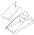
제2도는 본 발명의 일 실시예에 따른 소도체 등심 영상 획득기의 측면도이다.
제3도는 본 발명의 일 실시예에 따른 소도체 등심 영상 획득기의 바닥면을 보여주는 도면이다.
제4도는 본 발명의 일 실시예에 따른 소도체 등심 영상 획득기에서 카메라 촬영 방향을 보여주는 도면이다.
제5도는 카메라 높이에 따른 촬영 가능 영역을 보여주는 도면이다.
제6도는 뷰 각도 변화에 따른 카메라 높이 변화를 보여주는 도면이다.
제7도는 렌즈 회전부에 의한 뷰 각도 변화를 보여주는 도면이다.
제8도는 본 발명의 일 실시예에 따른 소도체 등심 자동판별 획득기의 상부면에 장착되는 조명 디스플레이 패널을 보여주는 도면이다.
제9도는 조명 디스플레이 패널의 밝기를 일정하게 했을 때 촬영 이미지를 보여주는 도면이다.
제10도는 본 발명의 다른 실시예에 따른 소도체 등심 자동판별 획득기를 보여주는 도면이다.
제11도는 본 발명의 또 다른 실시예에 따른 소도체 등심 자동판별 획득기를 보여주는 도면이다.
제12도와 제13도는 정보 디스플레이 패널에서 제공되는 예시적인 화면을 보여주는 도면이다.1 is a photograph showing the fillet measurement space.
2 is a side view of a small carcass fillet image acquirer according to an exemplary embodiment of the present invention.
3 is a view showing the bottom surface of the small conductor sirloin image acquirer according to an embodiment of the present invention.
4 is a diagram illustrating a camera photographing direction in a small conductor sirloin image acquirer according to an exemplary embodiment.
5 is a diagram illustrating a photographable area according to a camera height.
6 is a view illustrating a change in camera height according to a change in a view angle.
7 is a view illustrating a change in the view angle caused by the lens rotating part.
8 is a view showing a light display panel mounted on the upper surface of the small conductor fillet automatic discrimination obtainer according to an embodiment of the present invention.
9 is a view showing a photographed image when the brightness of the illumination display panel is made constant.
10 is a view showing a small conductor fillet automatic discrimination obtainer according to another embodiment of the present invention.
11 is a view showing a small conductor fillet automatic discrimination obtainer according to another embodiment of the present invention.
12 and 13 illustrate exemplary screens provided in an information display panel.
이하, 첨부된 도면들을 참조하여 본 발명에 따른 소도체 등심 영상 획득기에 대해 상세히 설명하도록 한다.Hereinafter, with reference to the accompanying drawings to be described in detail the small conductor sirloin image acquirer according to the present invention.
하기의 설명에서는 본 발명의 실시예에 따른 소도체 등심 영상 획득기를 이해하는데 필요한 부분만이 설명되며 그 이외 부분의 설명은 본 발명의 요지를 흩뜨리지 않도록 생략될 수 있다.In the following description, only parts necessary for understanding the small conductor fillet image acquirer according to an exemplary embodiment of the present invention will be described, and descriptions of other parts may be omitted so as not to distract from the gist of the present invention.
또한, 이하에서 설명되는 본 명세서 및 청구범위에 사용된 용어나 단어는 통상적이거나 사전적인 의미로 한정해서 해석되어서는 아니 되며, 본 발명을 가장 적절하게 표현할 수 있도록 본 발명의 기술적 사상에 부합하는 의미와 개념으로 해석되어야 한다.In addition, the terms or words used in the specification and claims described below are not to be construed as being limited to the ordinary or dictionary meanings, meaning that corresponds to the technical spirit of the present invention so that the present invention can be most appropriately expressed It should be interpreted as and concepts.
명세서 전체에서, 어떤 부분이 어떤 구성요소를 "포함"한다고 할 때, 이는 특별히 반대되는 기재가 없는 한 다른 구성요소를 제외하는 것이 아니라 다른 구성요소를 더 포함할 수 있는 것을 의미한다. Throughout the specification, when a part is said to "include" a certain component, it means that it can further include other components, except to exclude other components unless specifically stated otherwise.
여러 실시예에 있어서, 동일한 구성을 가지는 구성요소에 대해서는 동일한 부호를 사용하여 대표적으로 일 실시예에서 설명하고, 그 외의 실시예에서는 일 실시예와 다른 구성에 대해서 설명하기로 한다.In various embodiments, components having the same configuration will be representatively described in one embodiment using the same reference numerals, and other embodiments will be described with respect to components different from one embodiment.
도 2에 본 발명의 일 실시예에 따른 소도체 등심 영상 획득기(100)가 도시되어 있다. 2 shows a small conductor sirloin image acquirer 100 according to an embodiment of the present invention.
도 2에 도시된 바와 같이 본 발명의 일 실시예에 따른 소도체 등심 영상 획득기(100)는 바닥면(11), 바닥면과 90도 이하의 각도를 이루는 상부면(12) 및 바닥면과 상부면을 연결하는 측면들을 갖는 하우징(10)을 포함하여 이루어진다.As shown in FIG. 2, the small conductor sirloin image acquirer 100 according to an exemplary embodiment of the present invention may include a
바닥면(11)과 상부면(12)은 하우징(10)이 등심 측정 공간(S) 내에 삽입될 수 있도록 등심 측정 공간(S)에 대응하는 90도 이하의 적절한 각도(바람직하게는 θ는 30도 내지 40도)를 이룬다.The
또한 바닥면(11)과 상부면(12)이 만나는 일측이 등심 측정 공간(S) 안쪽에 위치하도록 하우징(10)이 도 1에 도시된 바와 같은 등심 측정 공간(S) 내에 삽입된다.In addition, the
본 발명의 일 실시예에 따른 소도체 등심 영상 획득기(100)는 이와 같이 등심 측정 공간(S) 내에 삽입된 상태에서 바닥면(11) 아래에 위치한 등심쪽의 절개면(즉 등급판정부위)을 촬영해야 한다. 이를 위해 도 3에 도시된 바와 같이 하우징의 바닥면(11)에는 투명창(1)이 마련되어 있다. The small conductor sirloin
또한 본 발명의 일 실시예에 따른 소도체 등심 영상 획득기(100)는 도 4에 도시된 바와 같이 투명창(1)을 90도 미만(바람직하게는 30도 내지 65도)의 비스듬한 각도로 내려다 보는 위치에서 촬영하는 카메라(30)를 구비한다. 도 4에서는 카메라 각도를 보여줄 수 있도록 상부면(12)을 제거한 상태를 도시하고 있음을 이해할 수 있을 것이다.In addition, the small conductor wick
이러한 카메라의 높이와 각도는 투명창의 전체 영역을 촬영할 수 있는 위치로 결정된다. 그러나 카메라 렌즈의 중심면(광축과 수직면이면서 렌즈의 중심이 되는 면)과 이미지 투영면이 평행한 일반 카메라를 사용할 경우 하우징의 높이(H)가 너무 높아져 휴대가 용이한 컴팩트한 사이즈의 소도체 등심 영상 획득기(100)를 구현하기 어려운 문제가 있다. 특히 경우에 따라서는 등심 측정 공간(S)에 하우징을 삽입하지 못할 우려도 있다.The height and angle of the camera are determined to be able to photograph the entire area of the transparent window. However, in case of using a general camera in which the center plane of the camera lens (the plane perpendicular to the optical axis and the center of the lens) and the image projection plane are parallel, the height (H) of the housing is too high, so the compact size of the core material is easy to carry There is a problem that is difficult to implement the acquirer (100). In particular, there is a possibility that the housing cannot be inserted into the fillet measuring space S in some cases.
하지만 이러한 문제를 해결하기 위해 하우징의 높이만 낮출 경우 도 5에 도시된 바와 같이 투명창의 일부 영역밖에 촬영할 수 없는 문제가 발생한다.However, when only the height of the housing is lowered to solve this problem, as shown in FIG. 5, only a part of the transparent window may be photographed.
이에 본 발명의 일 실시예에 따른 소도체 등심 영상 획득기(100)는 도 6에 도시된 바와 같이 바닥면에 대한 카메라의 뷰 각도를 줄여 바닥면에서 카메라까지의 높이가 줄어들도록 구성하였다(θ1〉θ2, h1〉h2). 그러나 이런 경우 바닥면에 대한 카메라의 뷰 각도가 비정상적으로 기울어진 상태에서 이미지를 획득하여야 하므로 초점이 잘 맞지 않는 문제가 발생한다.Accordingly, as shown in FIG. 6, the small conductor wick image acquirer 100 according to an exemplary embodiment of the present invention is configured to reduce the height of the camera from the floor to the camera by reducing the view angle of the camera with respect to the floor (θ). 1 > θ 2 , h 1 > h 2 ). However, in this case, the image needs to be acquired in a state in which the camera's viewing angle with respect to the floor is abnormally inclined, which causes a problem of poor focusing.
따라서 본 발명의 일 실시예에 따른 소도체 등심 영상 획득기(100)는 뷰 각도가 커지도록(θ3〉θ2) 도 7에 도시된 바와 같이 바닥면(11)에 대한 카메라 렌즈의 중심면 각도를 회전시키는 렌즈 회전부(미도시)를 구비하여 카메라와 바닥면 사이의 높이가 줄어들더라도 초점이 맞는 이미지를 획득할 수 있도록 하였다.Accordingly, the small conductor wick image acquirer 100 according to the exemplary embodiment of the present invention has a center plane of the camera lens with respect to the
이때 렌즈 회전부는 카메라 렌즈의 중심면(P1)과 이미지 투영면(P2)의 교차선이 초점이 맞아야 하는 등심쪽의 절개면(즉 등급판정부위)에 형성되도록 바람직하게 렌즈의 중심면을 회전시켜 보다 초점이 선명한 이미지를 획득할 수 있도록 하는 것이 더욱 바람직하다.In this case, the lens rotation part preferably rotates the center plane of the lens such that the intersection line between the center plane P1 of the camera lens and the image projection plane P2 is formed on the incision surface (ie, on the grading plate) on the side of the loin which should be in focus. It is further desirable to be able to obtain an image with a sharp focus.
다음으로 본 발명의 일 실시예에 따른 소도체 등심 영상 획득기(100)는 하우징 내부 상부면 상에 위치하는 조명 디스플레이 패널(20)을 구비한다. Next, the small conductor
조명 디스플레이 패널은 하우징이 등심 측정 공간(S) 내에 삽입된 상태에서 카메라(30)가 바닥면(11) 아래에 위치한 등심쪽의 절개면(즉 등급판정부위)을 촬영하기 위한 빛을 제공한다.The lighting display panel provides light for capturing the cut surface (ie, the grading plate) of the fillet positioned below the
본 발명의 일 실시예에 따른 소도체 등심 영상 획득기(100)는 투명창의 모든 영역에 균일한 빛을 제공하기 위해 도 8에 도시된 바와 같이 하우징 내부 상부면 상에 조명 디스플레이 패널(20)을 위치시킨다. 이때 조명 디스플레이 패널의 화면이 하우징 안쪽을 바라보도록 위치시킨다.In order to provide uniform light to all areas of the transparent window, the small conductor
그러나 본 발명의 일 실시예에 따른 소도체 등심 영상 획득기의 하우징은 바닥면과 상부면이 평행하지 않고 바닥면의 일측에서 타측으로 갈수록 상부면이 바닥면과 이격되도록 형성되어 있다.However, the housing of the small conductor wick image acquirer according to an embodiment of the present invention is formed such that the top surface is not parallel to the bottom surface and the top surface is spaced apart from the bottom surface from one side of the bottom surface to the other side.
따라서 상부면에 위치한 조명의 밝기를 일정하게 할 경우 도 9에 도시된 바와 같이 상부면과 가까운 일측의 이미지가 상부면과 먼 타측의 이미지보다 밝게 나타나는 이미지 왜곡이 발생한다.Therefore, when the brightness of the light located on the upper surface is made constant, as shown in FIG. 9, image distortion occurs in which an image of one side near the upper surface is brighter than an image of the other side far from the upper surface.
이에 본 발명의 일 실시예에 따른 소도체 등심 영상 획득기(100)는 조명 디스플레이 패널(20)을 제어하는 제어부(40)를 구비하여 카메라가 투명창(1)을 통해 소도체 등심 영상을 촬영할 때 촬영 전체 영역의 조도가 균일하게 되도록 상기 조명 디스플레이 패널의 밝기를 제어한다.Accordingly, the small conductor
보다 구체적으로 도 9에 도시된 바와 같이 조명 디스플레이 패널의 밝기를 동일하게 할 때 조명 디스플레이 패널과 가까운 바닥면 쪽의 이미지가 상대적으로 밝게 나타나므로 제어부는 바닥면과 가까운 조명 디스플레이 패널의 일측에서 바닥면과 먼 조명 디스플레이 패널의 타측으로 갈수록 밝기가 점진적으로 밝아지도록 제어할 수 있다.More specifically, as shown in FIG. 9, when the brightness of the lighting display panel is the same, the image of the bottom surface close to the lighting display panel appears relatively bright, so that the control unit is located on one side of the lighting display panel close to the bottom surface. The brightness of the display panel may be controlled to gradually increase toward the other side of the display panel.
특히 본 발명의 일 실시예에 따른 소도체 등심 영상 획득기는 도 8에 도시된 바와 같이, LCD, PDP 등과 같이 픽셀 단위로 밝기, 대조, 컬러 조정이 가능한 평판 디스플레이 패널을 조명으로서 사용한다. 따라서 제어부(40)는 조명 디스플레이 패널의 픽셀 중 상기 투명창에 가까운 픽셀보다 먼 픽셀의 밝기가 더 밝도록 픽셀 단위로 밝기를 조정하여 촬영 전체 영역의 조도가 균일하게 되도록 조명 디스플레이 패널의 밝기를 용이하게 제어할 수 있다.In particular, as shown in FIG. 8, the small-conductor fillet image acquirer according to an exemplary embodiment of the present invention uses a flat panel display panel capable of adjusting brightness, contrast, and color on a pixel-by-pixel basis, such as an LCD and a PDP. Therefore, the
또한 본 발명의 일 실시예에 따른 소도체 등심 영상 획득기의 제어부(40)는 카메라(30)에 의해 비스듬한 방향에서 촬영된 소도체 등심 영상을 영상처리하여 수직 상부에서 촬영한 것과 같이 보정할 수 있으며, 소도체 등심 등급을 자동 판정할 수 있도록 프로그램되어 있을 수 있다.In addition, the
또한 본 발명의 일 실시예에 따른 소도체 등심 영상 획득기에는 통신부(50)가 구비되어 소도체 등심 영상 획득기에 의해 촬영된 소도체 등심 영상, 제어부에 의해 보정된 보정 영상, 제어부에 의해 자동 판정된 소도체 등심 등급 정보 등을 외부로 전송할 수 있다.In addition, the small conductor wick image acquirer according to an embodiment of the present invention is provided with a
도 10에 본 발명의 다른 실시예에 따른 소도체 등심 영상 획득기(100')가 도시되어 있다. 10 illustrates a small conductor
본 발명의 다른 실시예에 따른 소도체 등심 영상 획득기(100')는 앞서 설명한 본 발명의 일 실시예에 따른 소도체 등심 영상 획득기(100)와 동일하게 투명창을 구비한 바닥면 및 조명 디스플레이 패널을 구비한 상부면을 갖는 하우징에 투명창을 90도 미만의 비스듬한 각도에서 촬영하는 카메라를 구비하고 있다. 또한 제어부 및 통신부를 구비할 수 있다.According to another exemplary embodiment of the present invention, the small conductor
다만 본 발명의 다른 실시예에 따른 소도체 등심 영상 획득기(100')는 도 10에 도시된 바와 같이 하우징의 일측에 손잡이(60)를 더 포함하는 것을 특징으로 한다.However, the small conductor
손잡이(60)는 사용자가 손잡이를 잡음으로써 본 발명의 다른 실시예에 따른 소도체 등심 영상 획득기를 용이하게 들고 있거나 이동시킬 수 있도록 한다.The
또한 도 10에 도시된 바와 같이 손잡이에 카메라 작동 버튼(61)이 구비되도록 하여 사용자가 손잡이를 잡아 소도체 등심 영상 획득기(100')를 들고 있는 상태에서 카메라 작동 버튼을 눌러 카메라를 작동시킴으로써 용이하게 소도체 등심 영상 이미지를 획득할 수 있도록 할 수 있다.In addition, the
도 11에 본 발명의 또 다른 실시예에 따른 소도체 등심 영상 획득기(100")가 도시되어 있다. 11 illustrates a small conductor
본 발명의 또 다른 실시예에 따른 소도체 등심 영상 획득기(100")는 도 10에 도시된 본 발명의 다른 실시예에 따른 소도체 등심 영상 획득기(100')와 동일하게 투명창을 구비한 바닥면 및 조명 디스플레이 패널(20)을 구비한 상부면을 갖는 하우징에 투명창을 90도 미만의 비스듬한 각도에서 촬영하는 카메라(30)와 손잡이(40)를 구비하고 있다.The small conductor
다만 본 발명의 또 다른 실시예에 따른 소도체 등심 영상 획득기(100")는 도 11에 도시된 바와 같이 카메라(30)에 의해 획득된 소도체 등심 영상을 사용자가 현장에서 바로 확인할 수 있도록 제공하는 정보 디스플레이 패널(70)을 더 포함하는 것을 특징으로 한다.However, the small conductor
정보 디스플레이 패널(70)은 도 12에 도시된 바와 같이 카메라(30)에 의해 촬영된 영상, 제어부에 의해 보정된 보정 영상 등을 제공할 수 있으며, 사용자가 정보 디스플레이 패널을 통해 제공되는 영상을 보고 해당 영상의 채택 및 삭제를 선택할 수 있는 선택기능을 제공할 수 있다. 이를 위해 정보 디스플레이 패널은 터치 패널로 마련되는 것이 바람직하다.As shown in FIG. 12, the
또한 정보 디스플레이 패널은 사용자가 채택한 영상을 외부로 전송하는 것에 대한 선택기능을 제공할 수 있다. 사용자가 외부 전송을 선택하게 되면 채택한 영상은 통신부를 통해 외부 서버 등으로 전송되며, 도 18에 도시된 바와 같이 전송 결과가 정보 디스플레이 패널(70)을 통해 제공될 수 있다.In addition, the information display panel may provide a selection function for transmitting the image adopted by the user to the outside. When the user selects an external transmission, the adopted image is transmitted to an external server through a communication unit, and as shown in FIG. 18, the transmission result may be provided through the
지금까지 본 발명의 실시예에 따른 소도체 등심 자동판별 획득기를 구체적인 실시예를 참고로 한정되게 설명하였다. 그러나 본 발명은 이러한 구체적인 실시예에 한정되지 않으며, 특허청구범위에 청구된 발명의 사상 및 그 영역을 이탈하지 않으면서 다양한 변화 및 변경이 있을 수 있음을 이해하여야 할 것이다.Up to now, a small conductor fillet automatic discrimination obtainer according to an embodiment of the present invention has been described with reference to specific embodiments. However, it is to be understood that the invention is not limited to these specific embodiments, and that various changes and modifications can be made without departing from the spirit and scope of the invention as claimed in the claims.
1: 투명창 10: 하우징
11: 바닥면 12: 상부면
20: 조명 디스플레이 패널 30: 카메라
40: 제어부 50: 통신부
60: 손잡이 61: 카메라 작동 버튼
70: 정보 디스플레이 패널1: transparent window 10: housing
11: bottom face 12: top face
20: light display panel 30: camera
40: control unit 50: communication unit
60: Handle 61: Camera Operation Button
70: information display panel
Claims (10)
상기 하우징 내부의 상기 상부면 상에 위치하는 조명 디스플레이 패널;
상기 투명창을 90도 미만의 각도로 내려다 보는 위치에서 촬영하는 카메라; 및
상기 조명 디스플레이 패널을 제어하는 제어부;
를 포함하여 이루어지고,
상기 조명 디스플레이 패널은 픽셀 단위로 색상 및 밝기 조정이 가능한 평판형 디스플레이 패널이며,
상기 제어부는 상기 조명 디스플레이 패널의 픽셀 중 상기 투명창에 가까운 픽셀보다 먼 픽셀의 밝기가 더 밝도록 제어하는 소도체 등심 영상 획득기.A housing having a bottom surface having a transparent window, a top surface having an angle of less than 90 degrees with the bottom surface, and side surfaces connecting the bottom surface and the top surface;
An illumination display panel positioned on the upper surface of the housing;
A camera for photographing at a position of looking down the transparent window at an angle of less than 90 degrees; And
A controller for controlling the illumination display panel;
It is made, including
The illuminated display panel is a flat panel display panel that can adjust the color and brightness in units of pixels,
And the controller controls the brightness of a distant pixel to be brighter than a pixel close to the transparent window among pixels of the illumination display panel.
상기 카메라는 렌즈의 중심면과 상기 바닥면이 이루는 각도를 조절하는 렌즈 회전부를 포함하는 소도체 등심 영상 획득기.The method of claim 1,
The camera is a small conductor core image acquisition device including a lens rotating portion for adjusting the angle between the center surface and the bottom surface of the lens.
상기 바닥면과 상부면은 30도 내지 40도 각도를 이루는 소도체 등심 영상 획득기.The method of claim 1,
The bottom surface and the upper surface is a small conductor sirloin image acquirer having an angle of 30 degrees to 40 degrees.
상기 바닥면에 대한 상기 카메라의 뷰각도는 30도 내지 65도인 소도체 등심 영상 획득기.The method of claim 1,
The angle of view of the camera relative to the bottom surface is 30 to 65 degrees small carcass fillet image acquirer.
상기 하우징의 일측에 연결된 손잡이를 더 포함하고,
상기 손잡이에는 상기 카메라 작동 버튼이 구비되어 있는 소도체 등심 영상 획득기.The method according to any one of claims 1 to 4,
Further comprising a handle connected to one side of the housing,
The handle is provided with a small carcass sirloin image is provided with the camera operation button.
상기 하우징의 외부에 정보 디스플레이 패널을 더 포함하고,
상기 정보 디스플레이 패널은 상기 카메라 작동 버튼의 동작에 따라 촬영된 이미지를 보여주는 소도체 등심 영상 획득기.The method of claim 7, wherein
An information display panel outside the housing;
The information display panel is a small conductor sirloin image acquirer showing an image taken in accordance with the operation of the camera operation button.
상기 정보 디스플레이 패널은 촬영된 이미지의 채택, 삭제를 선택할 수 있는 선택기능을 제공하는 소도체 등심 영상 획득기.The method of claim 8,
And the information display panel provides a selection function for selecting the adoption and deletion of the photographed image.
상기 카메라에 의해 촬영된 이미지를 외부로 전송하는 통신부를 더 포함하는 소도체 등심 영상 획득기.The method of claim 1,
A small conductor sirloin image acquirer further comprising a communication unit configured to transmit an image photographed by the camera to the outside.
Priority Applications (1)
| Application Number | Priority Date | Filing Date | Title |
|---|---|---|---|
| KR1020180038729A KR102087822B1 (en) | 2018-04-03 | 2018-04-03 | Apparatus for obtaining image of Beef Sirloin |
Applications Claiming Priority (1)
| Application Number | Priority Date | Filing Date | Title |
|---|---|---|---|
| KR1020180038729A KR102087822B1 (en) | 2018-04-03 | 2018-04-03 | Apparatus for obtaining image of Beef Sirloin |
Publications (2)
| Publication Number | Publication Date |
|---|---|
| KR20190115712A KR20190115712A (en) | 2019-10-14 |
| KR102087822B1 true KR102087822B1 (en) | 2020-03-11 |
Family
ID=68171585
Family Applications (1)
| Application Number | Title | Priority Date | Filing Date |
|---|---|---|---|
| KR1020180038729A Active KR102087822B1 (en) | 2018-04-03 | 2018-04-03 | Apparatus for obtaining image of Beef Sirloin |
Country Status (1)
| Country | Link |
|---|---|
| KR (1) | KR102087822B1 (en) |
Cited By (1)
| Publication number | Priority date | Publication date | Assignee | Title |
|---|---|---|---|---|
| KR20230061654A (en) | 2021-10-28 | 2023-05-09 | 축산물품질평가원 | Apparatus for obtaining image of beef sirloin |
Families Citing this family (1)
| Publication number | Priority date | Publication date | Assignee | Title |
|---|---|---|---|---|
| KR102586231B1 (en) * | 2020-12-18 | 2023-10-10 | 대한민국 | Automatic quality grade determination system and method using image information of cattle carcass, and Computer readable recording medium storing program performing the method |
Citations (1)
| Publication number | Priority date | Publication date | Assignee | Title |
|---|---|---|---|---|
| JP2015115918A (en) * | 2013-12-16 | 2015-06-22 | 新日鐵住金株式会社 | Imaging apparatus and imaging method |
Family Cites Families (2)
| Publication number | Priority date | Publication date | Assignee | Title |
|---|---|---|---|---|
| KR101631712B1 (en) * | 2009-06-04 | 2016-06-17 | 엘지전자 주식회사 | Lighting module with led |
| KR20150142289A (en) * | 2014-06-11 | 2015-12-22 | 주식회사 써비코씨엔에스 | Imaging apparatus for medical diagnosis |
-
2018
- 2018-04-03 KR KR1020180038729A patent/KR102087822B1/en active Active
Patent Citations (1)
| Publication number | Priority date | Publication date | Assignee | Title |
|---|---|---|---|---|
| JP2015115918A (en) * | 2013-12-16 | 2015-06-22 | 新日鐵住金株式会社 | Imaging apparatus and imaging method |
Cited By (2)
| Publication number | Priority date | Publication date | Assignee | Title |
|---|---|---|---|---|
| KR20230061654A (en) | 2021-10-28 | 2023-05-09 | 축산물품질평가원 | Apparatus for obtaining image of beef sirloin |
| KR102554362B1 (en) * | 2021-10-28 | 2023-07-13 | 축산물품질평가원 | Apparatus for obtaining image of beef sirloin |
Also Published As
| Publication number | Publication date |
|---|---|
| KR20190115712A (en) | 2019-10-14 |
Similar Documents
| Publication | Publication Date | Title |
|---|---|---|
| US20160014316A1 (en) | Photography method using projecting light source and a photography element thereof | |
| US8743274B2 (en) | In-camera based method of detecting defect eye with high accuracy | |
| CN107018389B (en) | Image projection system, projector and control method of image projection system | |
| KR101533853B1 (en) | SYSTEM AND METHOD FOR PROVIDING DISPLAY ADJUSTMENT USING OPTICAL FEEDBACK AND IMPROVED DISPLAY QUALITY BY IMAGE PROCESSING | |
| US20130113975A1 (en) | Projector Image Correction Method and System | |
| CN107404637B (en) | Projector with a light source | |
| CN103338342A (en) | Self-adaption projector | |
| CN102006346A (en) | Projector device | |
| CN103118270B (en) | Camera testing device and camera testing method | |
| CN108604046B (en) | Photographic support device and working method thereof | |
| CN104853126A (en) | Projector and method of controlling projector | |
| KR102087822B1 (en) | Apparatus for obtaining image of Beef Sirloin | |
| KR20160145545A (en) | Method of enhanced alignment of two means of projection | |
| US8264523B2 (en) | Device for a videoconference communication and associated communication method | |
| CN105915728A (en) | Smart phone | |
| KR100780701B1 (en) | Automatic 3D image generating device and method | |
| CN101006721B (en) | Projector device | |
| JP2012235355A (en) | Network camera system and method of controlling the same | |
| CN117672125A (en) | LED screen correction method, device, equipment, medium, LED screen and system | |
| CN208836325U (en) | A real-time evaluation device for camera imaging quality | |
| CN110430363A (en) | Side light source applied to automated optical vision-based detection equipment adjusts system and method | |
| KR20150125246A (en) | Controlling method for setting of multiview camera and controlling apparatus for setting of multiview camera | |
| JP6196148B2 (en) | Defocus control device and defocus control method | |
| WO2022018898A1 (en) | Image-capture device and program | |
| KR100458431B1 (en) | Assembling and valuating apparatus of camera module and resolution valuating methode thereof |
Legal Events
| Date | Code | Title | Description |
|---|---|---|---|
| A201 | Request for examination | ||
| PA0109 | Patent application |
Patent event code: PA01091R01D Comment text: Patent Application Patent event date: 20180403 |
|
| PA0201 | Request for examination | ||
| E902 | Notification of reason for refusal | ||
| PE0902 | Notice of grounds for rejection |
Comment text: Notification of reason for refusal Patent event date: 20190717 Patent event code: PE09021S01D |
|
| PG1501 | Laying open of application | ||
| E701 | Decision to grant or registration of patent right | ||
| PE0701 | Decision of registration |
Patent event code: PE07011S01D Comment text: Decision to Grant Registration Patent event date: 20200227 |
|
| GRNT | Written decision to grant | ||
| PR0701 | Registration of establishment |
Comment text: Registration of Establishment Patent event date: 20200305 Patent event code: PR07011E01D |
|
| PR1002 | Payment of registration fee |
Payment date: 20200306 End annual number: 3 Start annual number: 1 |
|
| PG1601 | Publication of registration | ||
| PR1001 | Payment of annual fee |
Payment date: 20230201 Start annual number: 4 End annual number: 4 |
|
| PR1001 | Payment of annual fee |
Payment date: 20231227 Start annual number: 5 End annual number: 5 |